What this guide covers
What's in the kit — component by component
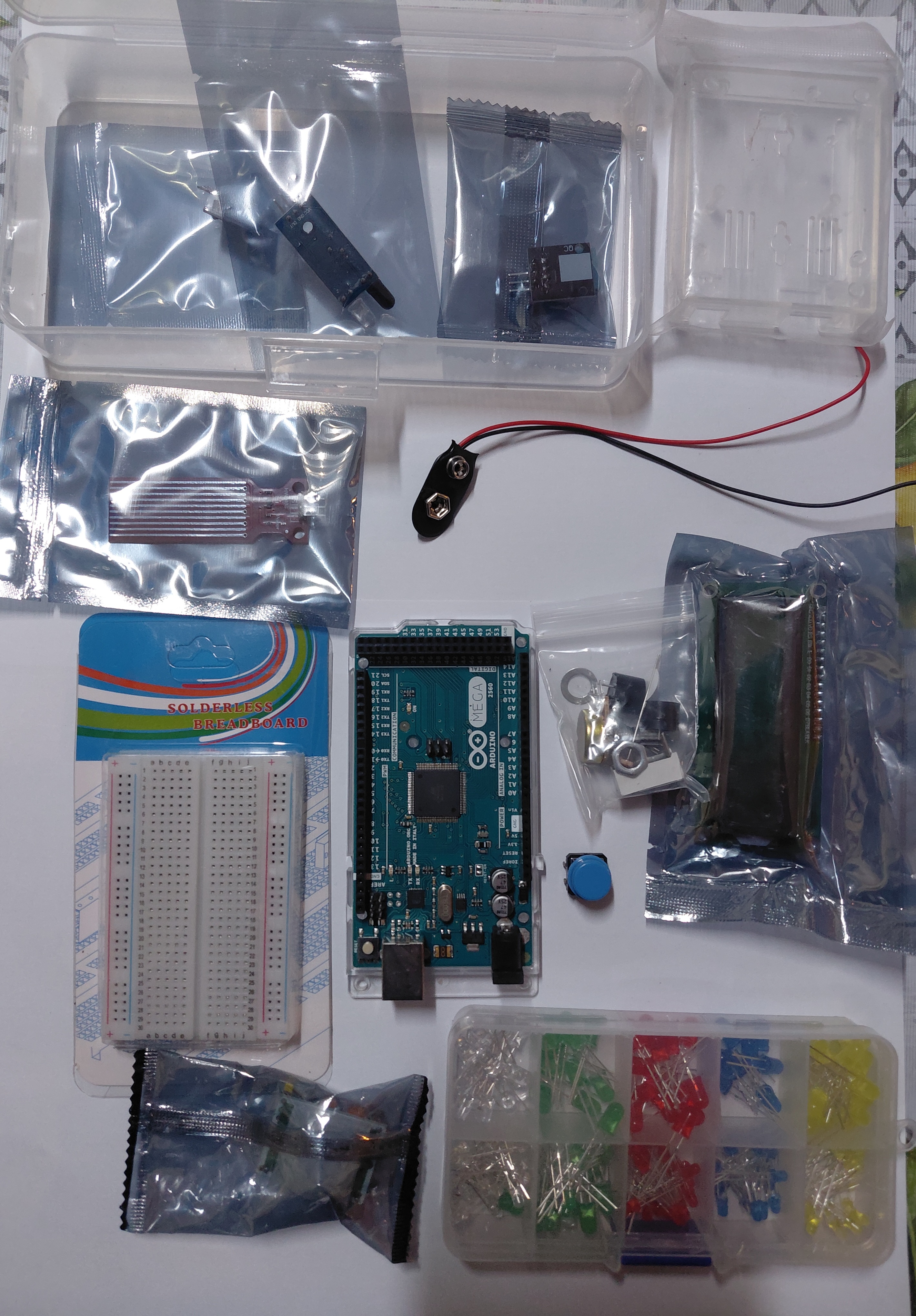
This is the kit as it arrived, photographed before opening anything. Not all starter kits are identical — vendors substitute components depending on stock — so I'm describing what's in this specific one, which is what the photo shows.
| Component | What it does | Beginner priority |
|---|---|---|
| Arduino Mega 2560 | The main board — 54 digital pins, 16 analog inputs, more memory than the Uno | ✅ Start here |
| Solderless breadboard | Lets you wire circuits without soldering — holes connect in rows | ✅ Start here |
| LED assortment (red, green, yellow, blue, white) | Output indicators — light up when a pin goes HIGH | ✅ Start here |
| Push button | Digital input — reads as HIGH or LOW depending on whether it's pressed | ✅ Week 2 |
| 9V battery clip | Powers the board without USB — connects to the barrel jack | ✅ Week 2 |
| Rain / moisture sensor | Analog sensor — outputs a voltage proportional to water on its surface | ⏳ Week 4+ |
| I2C interface module | Lets you control the LCD with only 2 wires instead of 6 | ⏳ Week 4+ |
| 16×2 LCD display | Text display — shows 2 lines of 16 characters each | ⏳ Week 4+ |
| Additional sensor modules (bagged) | Varies by kit — typically IR, temperature, or tilt sensors | ⏳ After basics |
The honest advice: leave the LCD, the I2C module and the rain sensor in their bags for the first two weeks. Every beginner class I've taught has at least one student who goes straight for the most complicated component and gets stuck, which kills motivation early. Start with LEDs — they give instant, visible feedback and can't damage anything if you wire them wrong (the LED just won't light, or it'll burn out and you replace it for a few cents).
Why Mega instead of Uno for this kit
The Arduino Uno is the standard beginner board and the one most tutorials are written for. The Mega 2560 is larger, has more pins, and costs a bit more. This kit ships with the Mega for a specific reason: the LCD + I2C module + sensors all running simultaneously would use most of the Uno's 14 digital pins, leaving little room for student experimentation. The Mega's 54 digital pins remove that constraint.
For the first three projects in this guide, the Mega and the Uno are functionally identical — pin numbers, code and wiring are the same. The difference only matters when you get to projects that use many components at once.
One thing the Mega does differently: its USB connector is the large square Type-B (printer-style) plug, not the smaller one on the Uno. If you're buying a cable separately, search for "USB Type-B" or "Arduino Mega cable" — a phone charger cable won't fit.
Which components to start with (and which to skip)
Based on running this kit in class, here is the order that works — not the order that looks most impressive:
- Single LED + resistor on a breadboard — one component, one pin, immediate result. Gets the IDE installed and the first successful upload done.
- Six LEDs in sequence — same concept scaled up. Introduces the idea of multiple outputs and leads naturally to loops.
- Button input — first time reading a digital input. Introduces
digitalRead()andifstatements with real hardware. - Rain sensor (analog) — first analog input,
analogRead(), and Serial Monitor for debugging. - LCD with I2C — first library installation, first
#include, first I2C address troubleshooting.
Students who try to jump straight to the LCD on day one spend the session installing the wrong library version and never see the screen light up. The order above means every session ends with something working.
Project 1 — single LED blink
Wire a single LED to pin 9 with a 220 Ω resistor in series (longer leg of the LED to the resistor, shorter leg to GND). This is the minimum viable circuit — one component beyond the board itself.
const int ledPIN = 9;

void setup() {
  Serial.begin(9600);       // iniciar puerto serie
  pinMode(ledPIN, OUTPUT);  // definir pin como salida
}

void loop() {
  digitalWrite(ledPIN, HIGH); // poner el Pin en HIGH
  delay(1000);                // esperar un segundo
  digitalWrite(ledPIN, LOW);  // poner el Pin en LOW
  delay(1000);                // esperar un segundo
}
What can go wrong and why: if the LED doesn't light, check the polarity first (the longer leg is the anode, goes toward the positive side). If the LED lights but doesn't blink, the upload may have failed silently — check the IDE output for error messages. If the LED glows faintly, the resistor value may be too high; try 100 Ω instead of 220 Ω with dim LEDs.
Project 2 — 6-LED sequence
Wire six LEDs to pins 2 through 7, each with its own 220 Ω resistor to GND. All six share the same GND rail on the breadboard. The sketch lights each one in order with a 1-second pause.
int led_Dos    = 2;
int led_Tres   = 3;
int led_Cuatro = 4;
int led_Cinco  = 5;
int led_Seis   = 6;
int led_Siete  = 7;

void setup() {
  Serial.begin(9600);             // iniciar puerto serie
  pinMode(led_Dos,    OUTPUT);    // definir pin como salida
  pinMode(led_Tres,   OUTPUT);
  pinMode(led_Cuatro, OUTPUT);
  pinMode(led_Cinco,  OUTPUT);
  pinMode(led_Seis,   OUTPUT);
  pinMode(led_Siete,  OUTPUT);
}

void loop() {
  digitalWrite(led_Dos,    HIGH); delay(1000); digitalWrite(led_Dos,    LOW); delay(1000);
  digitalWrite(led_Tres,   HIGH); delay(1000); digitalWrite(led_Tres,   LOW); delay(1000);
  digitalWrite(led_Cuatro, HIGH); delay(1000); digitalWrite(led_Cuatro, LOW); delay(1000);
  digitalWrite(led_Cinco,  HIGH); delay(1000); digitalWrite(led_Cinco,  LOW); delay(1000);
  digitalWrite(led_Seis,   HIGH); delay(1000); digitalWrite(led_Seis,   LOW); delay(1000);
  digitalWrite(led_Siete,  HIGH); delay(1000); digitalWrite(led_Siete,  LOW); delay(1000);
}
This sketch is intentionally verbose — the same four-line pattern repeated six times. That repetition is the teaching point. After it works, the next exercise is rewriting it with an array and a for loop to produce the same behavior in half the code:
// Refactored version using array + for loop
int leds[] = {2, 3, 4, 5, 6, 7};
int numLeds = 6;

void setup() {
  for (int i = 0; i < numLeds; i++) {
    pinMode(leds[i], OUTPUT);
  }
}

void loop() {
  for (int i = 0; i < numLeds; i++) {
    digitalWrite(leds[i], HIGH);
    delay(1000);
    digitalWrite(leds[i], LOW);
    delay(1000);
  }
}
Both versions produce identical behavior. Seeing the difference between them is more effective at teaching arrays than any explanation alone.
Project 3 — button-controlled LED
Wire the push button from pin 8 to GND, and enable the internal pull-up resistor in software (INPUT_PULLUP). Wire the LED to pin 9 as before. The LED lights when the button is held, goes off when released.
const int buttonPIN = 8;
const int ledPIN    = 9;

void setup() {
  Serial.begin(9600);
  pinMode(buttonPIN, INPUT_PULLUP); // use internal pull-up — no external resistor needed
  pinMode(ledPIN,    OUTPUT);
}

void loop() {
  int state = digitalRead(buttonPIN);
  // INPUT_PULLUP means LOW = pressed, HIGH = not pressed
  if (state == LOW) {
    digitalWrite(ledPIN, HIGH);
    Serial.println("Button pressed");
  } else {
    digitalWrite(ledPIN, LOW);
  }
}
The INPUT_PULLUP mode is worth explaining to students: without a pull-up or pull-down resistor, an unconnected input pin floats between HIGH and LOW unpredictably, causing the LED to flicker randomly. The internal pull-up holds the pin HIGH until the button connects it to GND. This is why the logic is inverted — LOW means pressed, HIGH means not pressed. Students find this counterintuitive the first time; the Serial Monitor output ("Button pressed") helps them confirm what's happening.
Components used across all three projects: Arduino Mega, solderless breadboard, 6× LEDs (any color from the kit's assortment), 6× 220 Ω resistors, 1× push button, jumper wires. The rain sensor, LCD and I2C module are not needed yet — leave them sealed until project 4 or 5.
FAQ
Can I use a different pin number for the LED?
Yes — any of the Mega's digital pins (2–53) work for digitalWrite. Pins 0 and 1 are reserved for serial communication (TX/RX) and cause problems if used for other purposes while the USB is connected. Pins 2–13 are the safest choice for beginners.
Do I need the exact resistor value listed?
Not exact, but close. 220 Ω is the standard value for 5 mm LEDs at 5 V. 100 Ω to 470 Ω all work — lower values make the LED brighter, higher values make it dimmer. Do not skip the resistor entirely: without it the LED draws too much current, overheats and burns out within seconds, and may damage the Arduino pin.
What does the rain sensor actually measure?
It measures electrical conductivity across its surface — water (especially tap water with dissolved minerals) conducts electricity, so the sensor's analog output voltage drops when wet. It is not a calibrated rainfall gauge; it detects presence of moisture, not quantity. We use it in class as an introduction to analog inputs (analogRead()) and the Serial Monitor for reading sensor values.
What I2C address does the LCD module use?
Most 16×2 LCD modules with the I2C backpack use address 0x27 or 0x3F. If the screen stays blank after uploading, run an I2C scanner sketch (freely available in the Arduino forums) to find the actual address, then update the LiquidCrystal_I2C lcd(0x27, 16, 2); line in your sketch accordingly. Address mismatch is the most common reason the LCD appears dead.
Can I power the Mega from the 9V battery clip in the kit?
Yes — the clip connects to the Mega's barrel jack (center-positive, 2.1 mm). A fresh 9V alkaline battery works for light loads (board + a few LEDs). If you add motors or many sensors, the 9V block drains fast and its internal resistance causes voltage sags that can reset the board. For anything beyond LED projects, use a rechargeable Li-ion pack or a wall adapter instead.
Kit photographed and tested in my classroom. No sponsored content or paid placements. The kit shown was purchased at market price for classroom use.
Next in this series
Once you have the LED projects running, see Arduino robotics in the classroom — the progression from LED sequence to a Bluetooth voice-controlled robot car, with the same hands-on approach.