What this guide covers
Belt drive vs gear drive: the short answer
For a lightweight desktop or educational robot arm, a synchronous timing-belt drive is often the most practical starting point. It is relatively quiet, inexpensive, easy to source and capable of placing the motor away from a moving joint. The belt must still be tensioned correctly, and the complete mechanism can flex under load.
For a compact high-torque joint, a geared transmission can be the better choice. Planetary gearboxes offer useful reduction in a small package, while strain-wave or harmonic reducers can provide high reduction ratios with very low measured backlash when correctly sized. They also cost more and have stricter requirements for alignment, lubrication and load limits.
There is no universal efficiency, backlash or service interval for either category. Values depend on ratio, speed, torque, belt width, pulley size, gear geometry, lubrication, temperature, mounting stiffness and duty cycle. Use manufacturer data for the selected component instead of copying a single percentage into a design.
I built the shoulder joint on my own prototype twice before landing on this recommendation. The first version used a GT2 belt at 4:1 because it was cheap and I had the pulleys on hand — it worked fine unloaded, but under a 0.6 kg payload the belt visibly deflected during acceleration, enough that the elbow's IK target was consistently off by a few millimeters. Swapping just that one joint to a small planetary gearbox fixed the positioning error without touching any other part of the arm.
How robot-arm transmissions work
Timing-belt drives
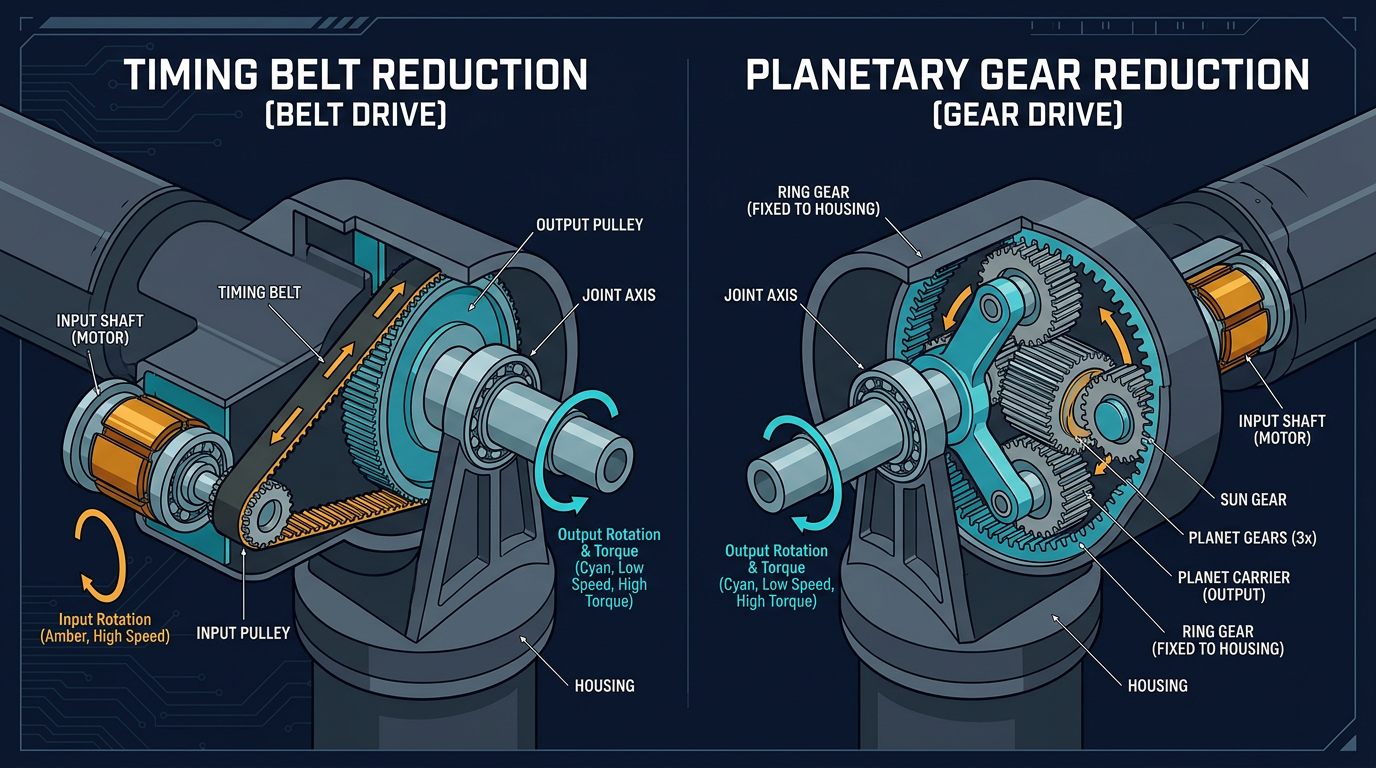
A synchronous belt uses molded teeth that engage matching pulley teeth. Unlike a friction V-belt, it is intended to transmit motion without normal slip. Common profiles include GT2, GT3, HTD and other manufacturer-specific geometries. The belt ratio is determined by pulley tooth counts:
Reduction ratio = driven pulley teeth ÷ driver pulley teeth.
A motor pulley with 20 teeth driving an 80-tooth joint pulley provides a 4:1 reduction. The output speed is approximately one quarter of motor speed, while ideal output torque is approximately four times motor torque before efficiency and compliance losses.
Planetary gearboxes
A planetary gearbox uses a sun gear, planet gears and a ring gear. Several teeth share the load, making the package compact for its torque capacity. Backlash, efficiency and allowable input speed vary substantially between models. A low-cost gearbox may be adequate for a prototype but not for a joint that reverses direction thousands of times per day.
Harmonic or strain-wave reducers
A strain-wave reducer uses a flexspline, circular spline and wave generator. It can deliver a high reduction ratio and low lost motion in a compact coaxial package. It is not automatically frictionless or maintenance-free: the flexspline has fatigue limits, bearings have load limits and the reducer must be installed according to the manufacturer's orientation and lubrication instructions.
Chain and roller drives
Roller chain is robust and tolerant of some contamination, but it is heavier, noisier and generally less suitable for a small wrist joint. It can work for a base or linear axis when the center distance is long and the environment makes a belt unsuitable. A chain needs correct slack, lubrication where specified and protection against pinch points.
Performance comparison
| Criterion | Timing belt | Planetary gear | Harmonic reducer | Chain |
|---|---|---|---|---|
| Mass | Low | Medium | Medium | High |
| Backlash | Low tooth clearance, but compliance possible | Low to moderate by grade | Very low lost motion in suitable models | Clearance and polygon effect possible |
| Torque density | Moderate | High | High | Moderate |
| Noise | Low to moderate | Depends on gear quality and speed | Low to moderate | Moderate to high |
| Cost | Low | Medium | High | Low to medium |
| Maintenance | Inspect tension, wear and alignment | Inspect lubrication, temperature and backlash | Follow service and lubrication instructions | Inspect slack, lubrication and elongation |
| Best fit | DIY arms, remote motors, light axes | Compact torque and general industrial joints | Precision joints with controlled lost motion | Long-center-distance or rugged mechanisms |
The table is a design guide, not a substitute for a datasheet. A wide, short belt can outperform a small gearbox in a particular application, while a high-quality planetary unit can be more repeatable than a poorly tensioned belt.
Torque, speed and reduction calculations
Start with the external load and the moving link mass. For a static estimate, joint torque is:
T = F × d
Here, F is force in newtons and d is the perpendicular distance from the joint axis to the center of mass. A 0.8 kg load at 0.20 m creates approximately 1.57 N·m before adding the link weight. The shoulder usually sees the combined effect of the payload, forearm, wrist and gripper.
Then include acceleration, friction and a design factor. For a first prototype, a factor of 1.5–2 can be a reasonable starting point, but it is not a safety certification. Use the actuator's continuous or rated torque for normal operation and reserve peak torque for acceleration or short transients. Stall torque should not be treated as a continuous rating.
For a reduction ratio R and transmission efficiency η:
Tout ≈ Tmotor × R × η
With a 0.4 N·m motor, a 4:1 belt reduction and an assumed efficiency of 0.90, ideal output torque is about 1.44 N·m. The real value may be lower because of belt tension, pulley bearing losses, acceleration and changing geometry.
Reduction also affects speed. If the motor runs at 3,000 rpm through a 4:1 reduction, the ideal output speed is 750 rpm. A robot joint may need much less speed, so check whether the chosen motor and reduction provide adequate resolution without creating excessive reflected inertia.
Choosing a transmission by robot-arm joint
Base rotation
A belt or chain can be useful when the motor needs to remain on the fixed base. A large driven pulley increases torque, but the base bearing must carry the radial and overturning loads. For a compact high-payload arm, a planetary or strain-wave reducer can simplify packaging.
Shoulder and elbow
These joints require the most torque because they lift downstream links. A belt can work well when the link is light and the belt path is supported by proper bearings. A gearbox is attractive when the joint must hold position with little compliance, but the motor and reducer add mass that the previous joint must also lift.
Wrist axes
Low-mass belt reductions can reduce the inertia carried by the elbow. Compact planetary or harmonic units are useful when the wrist needs high stiffness and a small envelope. Route cables so that wrist rotation does not twist them beyond their bend radius.
When a chain makes sense
Use chain when the center distance, contamination or mechanical environment favors it. Add guards around every moving chain and sprocket. For a clean desktop robot arm, a timing belt is usually quieter and easier to enclose.
Maintenance and inspection
Timing belts
- Inspect teeth for rounding, cracking, fraying, oil contamination and embedded debris.
- Check pulley alignment with a straightedge and confirm that flanges are not rubbing the belt.
- Verify tension using the belt manufacturer's method; "as tight as possible" is not a valid setting.
- Check that fasteners, keyways and clamps have not moved after repeated reversals.
- Replace a belt based on condition and the manufacturer's rated life, not on a universal hour number.
Gears and reducers
- Monitor temperature, noise, vibration and increasing lost motion.
- Check for lubricant leakage or contamination and follow the reducer's lubrication schedule.
- Measure backlash or repeatability at a defined load and approach direction.
- Confirm that external radial and axial loads stay within the reducer's bearing ratings.
- Do not disassemble a precision reducer without the manufacturer's procedure.
Chains and bearings
Measure chain slack and elongation, inspect sprocket wear and lubricate only where the chain specification allows it. For all transmissions, inspect bearings, shaft collars, set screws, printed mounts and guards. A loose fastener can look like a control problem even when the motor and firmware are correct.
Transmission troubleshooting
| Symptom | Possible cause | Check or correction |
|---|---|---|
| Arm misses position after reversals | Backlash, belt compliance or loose clamp | Approach targets from both directions, measure lost motion and inspect hubs. |
| Belt jumps teeth | Low tension, insufficient tooth engagement or overload | Verify pulley wrap, alignment, tension and peak torque. |
| Gearbox overheats | Excessive load, speed, misalignment or wrong lubricant | Compare actual duty to the datasheet and check bearing loads. |
| Drive is noisy | Resonance, worn teeth, poor alignment or high chain speed | Inspect the transmission unloaded, then under controlled load. |
| Joint feels stiff | Over-tensioned belt, shaft misalignment or bearing preload | Disconnect the actuator and rotate the joint by hand. |
| Repeatability degrades when warm | Thermal expansion, lubricant change or printed-part creep | Record temperature and repeatability over the complete duty cycle. |
The "arm misses position after reversals" row is the one I chased longest on my own build — it looked like a firmware bug for almost a week before I traced it to belt stretch combined with a slightly loose pulley set screw, not the motion planner.
Design checklist before purchasing
- Define payload, reach, cycle time, joint range and expected reversals per hour.
- Calculate the worst-case static and dynamic torque at each joint.
- Choose a reduction ratio that meets speed and resolution requirements.
- Check continuous torque, peak torque, radial load, axial load and allowable input speed.
- Estimate transmission compliance and backlash at the tool, not just at the motor shaft.
- Provide adjustment access for tensioners, fasteners and inspection.
- Protect belts, gears and chains from fingers, debris and accidental contact.
- Document the initial alignment, tension or backlash measurement for future maintenance.
Safety and responsible use
Open-frame robot arms can pinch, crush or throw a failed component. Test without a payload first, use low speed and keep an accessible power disconnect nearby. Add guards, emergency-stop functions and a documented risk assessment before allowing people to work near an automated arm.
A DIY transmission is appropriate for education and prototyping when its limits are understood. It should not be represented as industrial safety equipment without the required validation, guarding and compliance work.
Final thoughts
The belt-versus-gear decision comes down to what the joint actually needs: mass and cost savings favor belts, while compactness, torque density and controlled backlash favor gears or harmonic reducers. Most practical 6-DOF arms end up using both — belts for the lighter wrist axes where reflected inertia matters most, and gears or reducers for the shoulder and elbow where torque and stiffness dominate. Whichever you choose, size it from real torque calculations and manufacturer ratings, not from a single percentage borrowed from an unrelated project.
Frequently asked questions
Is a belt drive or gear drive better for a robot arm?
Neither is universally better. Timing belts are light, quiet and affordable for many desktop arms. Gears or harmonic reducers are preferable when compactness, high torque density, stiffness and controlled backlash matter more than cost.
Do belt drives have backlash?
A correctly tensioned synchronous belt has little tooth clearance, but the complete transmission can still show compliance from belt stretch, pulley runout, bearing play and mounting flex. It is not automatically backlash-free.
How do I calculate robot-arm transmission torque?
Estimate joint torque from load force multiplied by the perpendicular distance to the joint, then include link mass, acceleration, transmission efficiency and a safety factor. Use continuous and peak ratings rather than stall torque alone.
How often should a belt or gear drive be maintained?
There is no universal hour interval. Inspect components according to the manufacturer's documentation and the actual load, speed, contamination and duty cycle. Replace parts based on condition and rated life.
This article reflects the author's own build and troubleshooting experience, combined with publicly available manufacturer documentation. It does not contain sponsored placements or paid product endorsements.
Continue learning
For the wider mechanical architecture, see the 6-DOF Robot Arm Guide.
Primary sources and further reading
These references support the general engineering concepts in this guide. Component limits vary by variant and revision; check the governing datasheet.
Links checked: August 5, 2026.