Why Aluminum Remains the Default Material for Robot Arm Links
When engineers design the structural links that connect a 6-axis robot arm's joints, aluminum wins the material selection process more often than any alternative — not because it's the strongest or the lightest option available, but because it offers the best practical balance across strength-to-weight ratio, machinability, cost, and long-term dimensional stability under repeated cyclic loading.
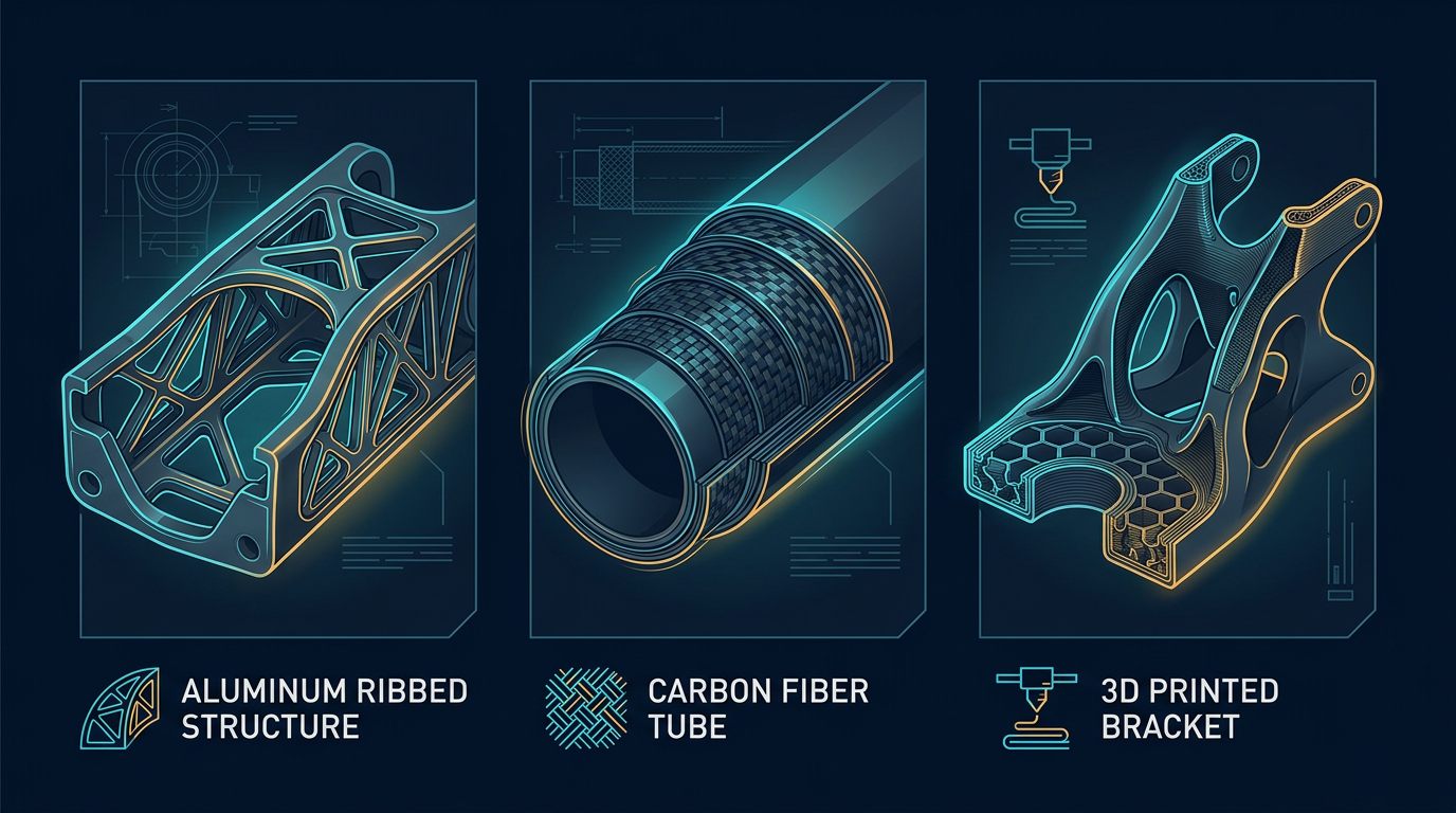
Steel links are stiffer per unit volume but roughly three times heavier for equivalent geometry, which directly increases the load every upstream joint and motor must move — a compounding penalty in a serial kinematic chain where the base joint has to accelerate the mass of every link above it. Carbon fiber offers a superior strength-to-weight ratio but at significantly higher cost and with layup consistency challenges that make it harder to justify for small-batch or one-off designs. 3D-printed polymer links are inexpensive and fast to iterate but fall far short on stiffness, dimensional stability under load, and long-term wear resistance at fastener interfaces.
Aluminum sits in the practical middle: readily CNC-machinable to tight tolerances, anodizable for wear and corrosion resistance, widely available in certified alloy stock, and forgiving enough in design that a competent CNC shop can produce a functional structural link on the first iteration.
On a forearm link I designed for a mid-size collaborative arm project, the first PLA prototype deflected visibly under a 4 kg static load test — enough that the end effector's position error exceeded what the encoder feedback could compensate for during a fast move. Switching that same geometry to 6061-T6, machined at a local job shop for about $140, brought deflection down to a level we couldn't measure with a dial indicator. That single swap is what convinced me aluminum is worth the extra cost once a build moves past a desktop demo.
Alloy Selection: 6061-T6 vs. 7075-T6
Not all aluminum is equivalent for structural robot links. The two alloys that come up repeatedly in industrial and hobbyist robot arm design each have distinct tradeoffs:
| Property | 6061-T6 | 7075-T6 |
|---|---|---|
| Tensile strength | ~310 MPa | ~570 MPa |
| Density | 2.70 g/cm³ | 2.81 g/cm³ |
| CNC machinability | Excellent | Good (more tool wear, more heat) |
| Weldability | Good | Poor (generally avoided) |
| Relative material cost | Baseline | 30-60% higher |
| Typical use case | Standard structural links, brackets, housings | Weight-critical links, high-stress wrist components |
For the vast majority of robot arm link designs — desktop, collaborative, and mid-size industrial — 6061-T6 is the correct default. Its machinability keeps CNC costs down, it anodizes cleanly, and its strength margin is more than adequate once proper wall thickness and rib design are applied. 7075-T6 earns its higher cost only in genuinely weight-critical applications, such as high-speed pick-and-place wrists where every gram of unsprung mass directly limits achievable acceleration. In practice, I've only specified 7075-T6 once, on a wrist link where the shop quoted noticeably longer cycle times and more tool changes than the equivalent 6061 part — worth knowing before you commit to it for a whole arm.
Wall Thickness and Structural Design Rules
Wall thickness is the single variable that most directly trades off weight against stiffness and fatigue life. The following ranges reflect standard practice for CNC-machined 6061-T6 structural links in robot arm applications:
- 3-5 mm for links carrying under 5 kg of end-effector payload — sufficient stiffness without excess mass for light-duty collaborative or desktop arms.
- 6-8 mm for links exceeding 10 kg payload, or spanning more than 400 mm between joint centers, where bending moment increases significantly with span length.
- 2 mm is acceptable only for non-structural covers, cable channels, or lightweight aesthetic panels — never for a primary load-bearing link, where it risks fatigue cracking around fastener bosses well before any static failure would occur.
Fatigue, not static yield strength, is usually the limiting factor in robot link design. A link that easily survives a single static load test can still crack after months of repeated acceleration cycles if stress concentrations around bolt holes, sharp internal corners, or thin transition sections aren't addressed with generous fillet radii and adequate boss thickness around every threaded connection. I learned this directly after a 3 mm wall link with a sharp internal corner near a bolt boss developed a hairline crack after roughly three weeks of intermittent testing — adding a 3 mm fillet at that corner on the next revision solved it permanently.
Weight Optimization: Pocketing and Topology Considerations
Reducing link mass has a compounding benefit through the kinematic chain — every gram removed from the wrist reduces the torque required at the elbow, shoulder, and base joints to accelerate it. The two most practical weight reduction techniques for CNC-machined links are:
Strategic Pocketing
Material located near a link's neutral bending axis contributes very little to overall bending stiffness, since stiffness is dominated by material distributed far from that axis (a direct consequence of the area moment of inertia calculation). Removing material from this low-contribution zone through pocketing can reduce link mass by 20-40% with minimal measurable loss in stiffness, provided the outer wall sections and rib structure remain intact.
Rib Reinforcement
Thin ribs oriented perpendicular to the primary bending direction restore much of the stiffness lost through pocketing at a fraction of the mass a solid wall would require. A honeycomb or triangulated rib pattern, common in aerospace-influenced designs, distributes load efficiently across the pocketed section without introducing the stress concentrations a poorly designed pocket edge would create.
These techniques are best guided by even a basic finite element analysis (FEA) simulation available in most modern CAD packages, rather than applied uniformly by eye — an FEA pass takes minutes and reliably identifies which regions of a link can be safely lightened versus which regions carry genuine structural load.
CNC Machining Considerations and Tolerances
Designing a link that machines efficiently is just as important as designing one that performs well mechanically. A few practical rules keep CNC quotes reasonable and lead times short:
- Minimize the number of setups. Every re-fixturing operation adds cost and introduces a potential source of dimensional error between machined faces. Design links so that as many features as possible can be reached from one or two orientations.
- Use standard tool radii for internal corners. Specifying a 3 mm or 6 mm internal fillet radius, matching common end mill diameters, avoids requiring specialty tooling that increases machining cost and lead time.
- Hold tight tolerances only where they matter. Bearing bores and joint mounting faces typically require tolerances in the ±0.02 to ±0.05 mm range; non-critical pocket depths and cosmetic features can be specified at standard ±0.1 mm to reduce machining time and cost.
- Design fastener bosses with adequate wall thickness around every threaded hole — a common failure point occurs when a pocket is placed too close to a bolt hole, leaving insufficient material to resist the clamping and cyclic load at that connection.
"The lightest possible link isn't the goal. The goal is the lightest link that still survives ten million duty cycles without a crack forming at a bolt boss nobody thought to reinforce."— Daniel Ferro, Mechanical Design Engineer
Fastening: Helicoils and Bolt Patterns
Aluminum's relative softness compared to steel makes thread durability a genuine design concern at every link-to-joint connection that gets assembled and disassembled during maintenance or upgrades.
- M4 or M5 hex bolts in grade 8.8 steel are standard for link-to-joint connections in light-to-mid-size robot arms, offering a good balance of clamping force and hole size relative to typical link wall thickness.
- Helicoil thread inserts (commonly M4×0.7 or M5×0.8) should be used in any aluminum threaded hole subject to repeated assembly or cyclic loading. A helicoil distributes thread engagement stress across a hardened steel coil rather than directly into the softer aluminum, dramatically reducing the risk of thread stripping over the link's service life.
- A 4-hole square bolt pattern at roughly 20 mm spacing is a common standard for joint interface flanges, providing resistance to both torsional and bending loads at the connection without requiring an oversized flange.
Anodizing Types Compared
Raw machined aluminum corrodes and wears faster than most engineers expect, particularly at pivot bores and sliding surfaces. Anodizing is an electrochemical process that grows a hard oxide layer on the aluminum surface, and the type selected has a real impact on durability and cost.
| Type | Typical Coating Thickness | Best For | Relative Cost |
|---|---|---|---|
| Type I (chromic acid) | 0.5 - 2.5 µm | Aerospace fatigue-sensitive parts; rarely used for robot links | Low |
| Type II (sulfuric acid) | 5 - 25 µm | General-purpose corrosion resistance and color options | Low-Moderate |
| Type III (hardcoat) | 25 - 100 µm | Wear surfaces, pivot bores, sliding interfaces | Moderate-High |
Type II anodizing is the correct default for the majority of a robot arm's exterior link surfaces — it's inexpensive, improves corrosion resistance, and is available in a range of colors useful for visually distinguishing cell components. Type III hardcoat should be specified selectively on high-wear features such as bearing bores or any surface subject to repeated sliding contact, where its significantly greater hardness meaningfully extends service life.
Aluminum vs. Carbon Fiber vs. Steel vs. 3D-Printed PLA
Choosing between materials for a robot link comes down to matching the application's priorities — cost, weight, stiffness, or production volume — against each material's practical tradeoffs.
| Material | Relative Stiffness | Relative Weight | Relative Cost (low volume) | Best Fit |
|---|---|---|---|---|
| 6061-T6 Aluminum | High (69 GPa) | Moderate | Moderate | Most industrial and collaborative links |
| Carbon Fiber Composite | Very High (up to 230 GPa) | Low | High | High-speed wrists, weight-critical arms |
| Steel (mild/alloy) | High (~200 GPa) | High | Low | Heavy-duty industrial base structures |
| 3D-Printed PLA | Low (~3.5 GPa) | Low | Very Low | Prototyping, education, non-load-bearing covers |
Aluminum's Young's modulus of approximately 69 GPa makes it roughly 20 times stiffer than typical PLA at around 3.5 GPa. For equivalent-weight structural links, this translates to roughly three times greater bending stiffness for aluminum versus PLA, since aluminum's superior stiffness-to-density ratio allows thinner walls that still outperform a thicker, heavier PLA equivalent. This is the core reason serious robot arm builds move away from 3D-printed structural links once payload and cycle-speed requirements exceed hobbyist levels.
Design Checklist Before Sending Links to CNC
- Confirm alloy selection matches the application's strength and cost requirements — 6061-T6 for most cases, 7075-T6 only for weight-critical designs.
- Verify wall thickness meets or exceeds the minimum for the intended payload class, with extra margin at fastener bosses.
- Run a basic FEA pass to confirm pocketing and rib placement doesn't create unexpected stress concentrations.
- Specify helicoil inserts on every threaded hole subject to disassembly or cyclic load.
- Use standard tool radii for internal corners to control CNC machining cost.
- Select the correct anodizing type per surface — Type II general purpose, Type III on wear surfaces.
- Request a first-article inspection report from your CNC supplier on critical bearing bore and mounting face dimensions before committing to a full production run.
Related Resources
- Robot Arm Payload Calculator: How to Size a 6-DOF Arm for Your Load
- The Complete 6-DOF Robot Arm Guide (2026)
Sources and References
- ASTM International — ASTM B221, standard specification for aluminum alloy extruded bars, rods, and shapes.
- ISO — ISO 9409-1, manipulating industrial robots mechanical interface specifications.
- Aluminum Association — 6061 and 7075 alloy datasheets, mechanical property references.
- International Federation of Robotics (IFR) — World Robotics Report, market and installation context.
This article reflects my own design experience and publicly available engineering references. It does not contain sponsored placements or paid product endorsements. If that changes in future updates, it will be clearly disclosed here.
Frequently Asked Questions
What is the recommended wall thickness for aluminum robot links?
3-5 mm for links under 5 kg payload; 6-8 mm for links exceeding 10 kg or spanning more than 400 mm. Use helicoil inserts (M4×0.7 or M5×0.8) for threaded connections in aluminum.
What aluminum alloy is recommended for CNC robot links?
6061-T6 is the standard for industrial robot links due to its strength-to-weight ratio (tensile strength ~310 MPa, density 2.7 g/cm³) and excellent CNC machinability with anodized finish. 7075-T6 is reserved for weight-critical applications.
How does aluminum stiffness compare to 3D-printed PLA?
Aluminum (Young's modulus 69 GPa) is approximately 20× stiffer than PLA (~3.5 GPa). For equivalent-weight structural links, aluminum provides roughly 3× higher bending stiffness due to combined material and geometric advantages.
Is anodizing necessary for aluminum robot arm links?
Strongly recommended for any link exposed to handling, moisture, or coolant. Type II anodizing provides general corrosion resistance at low cost; Type III hardcoat is recommended for high-wear surfaces like pivot bores.
Should I hollow out or pocket aluminum robot links to save weight?
Yes, strategic pocketing and rib reinforcement can remove 20-40% of a link's mass with minimal stiffness loss when guided by basic FEA analysis rather than removed uniformly by eye.