Interactive Robot Arm Payload Calculator
Enter your application's numbers below. The calculator runs entirely in your browser — nothing is uploaded or stored — and returns the minimum rated payload capacity you should look for when comparing robot arm specification sheets.
Default values reflect a typical mid-speed pick-and-place application. Replace them with your own part and tooling weights for an accurate result.
"Payload capacity on a spec sheet is a single number measured under specific conditions. Your actual application — reach distance, acceleration, and mounting orientation — determines whether that number applies to you."— Robotics Engineering, Mechanical Design Desk
Why Payload Sizing Mistakes Are So Common
Choosing a robot arm based on the headline payload number from a spec sheet is one of the most frequent and expensive mistakes made during automation planning. A robot advertised as a "10 kg payload" model does not mean it can safely and repeatably handle a 10 kg part in every configuration. That number is typically measured at a specific reach distance, with the load centered close to the wrist flange, under moderate acceleration — conditions that rarely match a real production task exactly.
Undersizing the payload leads to premature joint wear, positioning drift, and unexpected fault trips as the robot controller detects torque limits being approached. Oversizing wastes capital on a larger, more expensive robot than the application requires. The calculator above exists to close that gap by walking through the same static-plus-dynamic-plus-margin logic that mechanical engineers use during the sizing phase of a project.
The Formula Behind the Calculator
The payload sizing calculation used above follows three steps that mirror standard mechanical engineering practice for robot arm selection:
Step 1: Static Load
Static Load = Workpiece Weight + End-Effector Weight
This is the combined weight the wrist flange must support at rest. Most buyers correctly account for the part weight but forget to include the gripper, cabling, and any mounted sensors — all of which count against the robot's total rated payload.
Step 2: Dynamic Load
Dynamic Force (N) = Mass (kg) × Peak Acceleration (m/s²)
As the robot accelerates or decelerates the combined mass, Newton's second law applies: force equals mass times acceleration. This additional force acts on the joints on top of the static weight and must be included, particularly for fast cycle-time applications such as pick-and-place or electronics assembly, where accelerations of 4-8 m/s² are common.
Step 3: Apply a Safety Margin
Minimum Rated Payload = (Static Load + Dynamic Load Equivalent) × Safety Margin (typically 1.3×)
The safety margin absorbs uncertainty in your own weight measurements, accounts for future tooling or part changes, and keeps the robot operating comfortably below its absolute torque limits rather than at the edge of its rated capacity — which is where premature wear and unexpected faults occur.
Why Reach Reduces Effective Payload
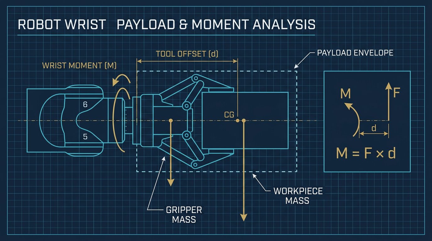
The payload number on a manufacturer's spec sheet is measured at a specific reference point, usually close to the wrist flange with a short offset. As the load is carried farther from that reference point — either because the workpiece extends past the gripper or because the robot is operating near its maximum radial reach — the torque applied to the shoulder and elbow joints increases proportionally.
Most manufacturers publish a payload-vs-reach derating curve or a load-moment diagram in their technical documentation showing how the maximum allowable payload decreases as the center of gravity moves farther from the mounting face. Always check this chart for the specific robot model you're evaluating — the headline payload number is a best-case figure, not a guarantee across the entire work envelope.
| Load Center of Gravity Offset | Typical Payload Derating | Practical Implication |
|---|---|---|
| 0 - 50 mm from flange | 0% (full rated payload) | Compact grippers, standard tooling |
| 50 - 150 mm from flange | 10% - 25% reduction | Long grippers, offset tooling, angled parts |
| 150 - 300 mm from flange | 25% - 50%+ reduction | Long reach tools, multi-part fixtures |
These figures are illustrative and vary by manufacturer and model — always confirm against the specific robot's load-moment diagram rather than assuming a linear derating relationship.
Understanding Dynamic Load in Real Applications
Dynamic load is easy to underestimate because it doesn't show up when the robot is standing still — it only appears during motion, and it scales directly with how aggressively the robot accelerates and decelerates. Two applications with identical part weights can require very different robot ratings purely based on cycle-time requirements:
- Slow, precise assembly (2 m/s² acceleration): A 5 kg combined load generates roughly 10 N of additional dynamic force — a modest addition to the static weight.
- High-speed pick-and-place (8 m/s² acceleration): The same 5 kg combined load generates roughly 40 N of additional dynamic force — four times greater, and enough to push a marginally-sized robot into fault conditions during peak cycles.
This is why two integrators sizing a robot for what looks like the same part weight can arrive at very different robot model recommendations — the deciding factor is often cycle time and acceleration profile, not the part itself.
Typical Payload Ranges by Robot Category
Once you have your minimum required payload from the calculator above, use the table below to identify which general category of robot arm is likely to fit your application before requesting detailed quotes.
| Category | Typical Payload | Typical Reach | Primary Application |
|---|---|---|---|
| Desktop / DIY | 0.5 - 2 kg | 300 - 700 mm | Education, rapid prototyping |
| Collaborative | 3 - 20 kg | 900 - 1,300 mm | Flexible assembly, packaging, machine tending |
| Mid-Size Industrial | 20 - 60 kg | 1,400 - 2,000 mm | Palletizing, material handling, dispensing |
| Heavy-Duty Industrial | 60 - 700+ kg | 1,650 - 3,500 mm | Spot welding, heavy part transfer, press tending |
Common Payload Sizing Mistakes
- Forgetting the end-effector weight entirely and sizing the robot based on part weight alone. Grippers, especially pneumatic or multi-finger designs, commonly weigh 1-4 kg on their own.
- Ignoring the reach-based derating curve and assuming the headline payload number applies at every position in the work envelope.
- Skipping the dynamic load calculation for high-speed applications, then discovering the robot faults or drifts out of tolerance once production cycle times are pushed to target speed.
- Selecting a robot right at the calculated minimum with no safety margin, leaving no room for a heavier replacement part, an added sensor, or a future tooling upgrade.
- Not accounting for orientation-dependent loading in applications where the robot's wrist must support a load at odd angles, which can change the effective torque compared to a straight vertical lift.
Related Resources
- Robot Arm ROI Calculator: Payback Period & TCO Guide
- Robot Arm Safety Standards: ANSI RIA, CSA Z434 & ISO Compliance
- Integrating 6-Axis Robot Arms with Siemens and Allen-Bradley PLCs
- The Complete 6-DOF Robot Arm Guide (2026)
Sources and References
- International Federation of Robotics (IFR) — World Robotics Report, payload and installation benchmark data.
- Robot manufacturer technical documentation — load-moment diagrams and payload-vs-reach derating charts, published by individual robot manufacturers for each model.
- ISO 9946 / ISO 10218-1 — industrial robot characteristics and load capacity verification methodology.
- Association for Advancing Automation (A3) — robot integration and application sizing best practices.
Frequently Asked Questions
How do I calculate the payload needed for a robot arm?
Add the weight of the workpiece to the weight of the end-effector (gripper or tool), then apply a safety margin, typically 1.3x, to account for dynamic loads generated during acceleration and deceleration. The result is the minimum rated payload the robot should have at your required reach distance.
Why does reach affect how much weight a robot arm can lift?
A robot's payload rating is usually specified at a reference center of gravity close to the wrist flange. As the load is carried farther from the base or positioned farther from the mounting face, the torque on the shoulder and elbow joints increases, which reduces the effective payload the arm can safely carry at that extended position.
What is a dynamic load factor and why does it matter?
A dynamic load factor accounts for the additional force generated when a robot accelerates or decelerates a mass, calculated as force equals mass times acceleration. High-speed applications such as pick-and-place or electronics assembly generate significant dynamic loads that must be added to the static weight when sizing the robot.
Should I always choose a robot with a payload rating higher than my calculated requirement?
Yes. Most integrators recommend selecting a robot with a rated payload at least 20 to 30 percent above the calculated requirement to allow for future tooling changes, part variations, and to keep the robot operating comfortably within its performance envelope.
Does payload rating include the weight of the gripper?
Yes. Manufacturer payload ratings are for total load at the wrist flange, which includes both the end-effector and the workpiece combined, not the workpiece alone. This is one of the most common sizing mistakes made when selecting a robot arm.
Primary sources and further reading
These references support the general engineering concepts in this guide. Component limits vary by variant and revision; check the governing datasheet.
Links checked: August 5, 2026.