Why PLC Integration Is the Hardest Part of a Robot Cell
Buying a 6-axis robot arm is the easy part. The engineering work that actually determines whether a cell runs reliably for ten years happens at the network and safety layer — the point where the robot controller has to talk to the plant's Siemens or Allen-Bradley PLC without dropping a signal during a 0.5-second pick-and-place cycle.
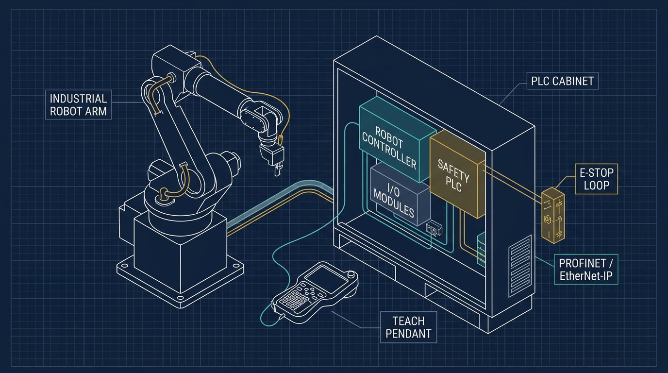
Most integration failures in North American plants are not mechanical. They come from mismatched network protocols, sloppy I/O tag naming between the robot teach pendant and the PLC program, or safety circuits that were "temporarily" jumpered during commissioning and never fixed. This guide walks through the three things that actually matter: choosing the right industrial network, mapping I/O correctly, and building a safety architecture that will pass a third-party audit.
PROFINET vs. EtherNet/IP: Which Network Should Drive Your Robot Cell?
The single biggest architectural decision in any robot-to-PLC integration is the fieldbus. In practice, the choice is rarely about which protocol is "better" — it's about which protocol your plant already standardized on.
- PROFINET is the default for plants running Siemens S7-1200/1500 PLCs programmed in TIA Portal. It uses a GSDML device file to describe the robot controller's I/O structure, supports cyclic real-time data exchange down to 1 ms, and integrates cleanly with Siemens' PROFIsafe protocol for safety-rated signals over the same cable.
- EtherNet/IP is the standard for Allen-Bradley ControlLogix and CompactLogix processors running Studio 5000. It relies on an EDS (Electronic Data Sheet) file for device configuration and uses CIP Safety for safety-rated I/O over the same physical network.
- Modbus TCP still shows up on older or budget-driven installations. It's simple and vendor-neutral but lacks native safety extensions, so it's rarely used for anything beyond non-safety status reporting.
- OPC-UA is increasingly layered on top of either network for MES/SCADA reporting — production counts, cycle-time analytics, and predictive maintenance data — without interfering with the deterministic control traffic.
Nearly every modern 6-axis robot controller (FANUC R-30iB, ABB IRC5, KUKA KR C5, Yaskawa DX200) ships with both PROFINET and EtherNet/IP as either a built-in option or an add-on card, so the network choice should follow the PLC fleet already installed on your floor — not the robot brand.
"The robot doesn't care which PLC it's talking to. The PLC doesn't care which robot brand sent the signal. What breaks the integration is inconsistent tag naming and undocumented I/O changes made during commissioning."— Field engineering note, Robotics Engineering integration review
Connecting a Robot Arm to a Siemens S7-1500 via PROFINET
A typical Siemens integration follows this sequence in TIA Portal:
- Install the GSDML file supplied by the robot manufacturer into TIA Portal's hardware catalog (Options → Manage General Station Description Files).
- Add the robot as a PROFINET I/O device under the S7-1500's network view and assign it a device name and IP address that matches the address configured on the robot controller's teach pendant.
- Configure the I/O module slots exactly as defined in the GSDML — most robot controllers expose a fixed block of input and output words (commonly 16, 32, or 64 bytes) that map to specific status and command bits.
- Set the PROFINET update time (send clock) — typically 1 ms to 4 ms for a robot cell — based on how many devices share the same network segment.
- Download the hardware configuration and verify the diagnostic LED on the robot's PROFINET port shows a green "RUN" state with no red diagnostic flags.
Connecting a Robot Arm to an Allen-Bradley PLC via EtherNet/IP
On a Rockwell platform, the process in Studio 5000 looks like this:
- Add the EDS file for the robot controller through the EDS Hardware Installation Tool.
- Create a new Ethernet module under the ControlLogix or CompactLogix I/O tree, entering the robot's fixed IP address and the correct Input/Output/Configuration assembly instance numbers from the robot vendor's integration manual.
- Set the Requested Packet Interval (RPI) — the EtherNet/IP equivalent of PROFINET's send clock — typically between 5 ms and 20 ms depending on cell complexity.
- Map the produced/consumed tags to a user-defined data type (UDT) in the Logix controller so operators and maintenance techs can read status bits by name (e.g., Robot01.Ready) instead of raw byte offsets.
- Download and go online, then verify the module status shows "Running" in the I/O tree with no yellow warning triangle.
I/O Mapping: The Handshake That Keeps the Cell Synchronized
Regardless of which network you choose, the robot and PLC exchange a small, well-defined set of signals on every cycle. Getting this handshake wrong is the number one cause of cells that "work in testing but fault randomly in production."
| Signal | Direction | Type | Purpose |
|---|---|---|---|
| Cycle_Start | PLC → Robot | Digital, pulsed | Tells the robot to begin the next program cycle |
| Robot_Ready | Robot → PLC | Digital, latched | Confirms the robot is in auto mode, no faults, home position |
| Program_Number | PLC → Robot | Integer (word) | Selects which stored robot program to run (part variant) |
| Cycle_Complete | Robot → PLC | Digital, pulsed | Signals the PLC that the robot finished its motion sequence |
| Fault_Code | Robot → PLC | Integer (word) | Reports a numeric fault for HMI diagnostics and MES logging |
| E-Stop_OK | Safety circuit → Both | Dual-channel safety | Confirms the safety chain is closed; not routed through standard I/O |
Best practice is to document every one of these tags in a shared spreadsheet before wiring begins, with identical names on both the robot's I/O configuration screen and the PLC's tag database. This single habit prevents the majority of commissioning delays on multi-vendor cells.
Safety Interlocks: Building a Category 4 / PL e Architecture
Safety signals should never share the same conductors or logic path as standard process I/O. For a robot cell rated to Category 4, Performance Level e under ISO 13849-1, the architecture typically includes:
- Dual-channel E-stop circuits wired through a safety relay (Pilz, Allen-Bradley Guardmaster) or a safety PLC (Siemens F-CPU, Allen-Bradley GuardLogix) with cross-monitoring to detect a shorted or stuck contact.
- Perimeter light curtains and area scanners that immediately remove drive power (STO — Safe Torque Off) from the robot's servo amplifiers when breached, rather than relying solely on a software-level pause.
- Interlocked access gates using safety-rated switches that cannot be defeated with a screwdriver or magnet, feeding into the same dual-channel safety chain as the E-stops.
- PROFIsafe or CIP Safety to carry safety-rated status bits over the same PROFINET or EtherNet/IP cable as standard I/O, without compromising the safety integrity level, provided the network switches and cabling are rated for the combined traffic.
- Documented risk assessment per ANSI RIA R15.06 (USA) or CSA Z434 (Canada), reviewed and signed off before the cell is released to production — insurers and OSHA/CSA inspectors will ask for this document.
A frequent audit failure is discovering that a "temporary" bypass jumper installed during commissioning was never removed. Every safety bypass should require a logged, time-limited maintenance override — never a permanent wire change.
Commissioning Checklist
- Confirm IP addressing scheme matches the plant network standard and doesn't collide with existing devices.
- Verify GSDML/EDS file version matches the robot controller's firmware version exactly.
- Test every I/O tag individually in manual mode before enabling automatic cycling.
- Force a network cable disconnect during testing to confirm the robot faults safely rather than continuing blind.
- Validate E-stop response time with a stopwatch or safety-rated test tool against the manufacturer's stated stopping category.
- Document final I/O map, IP addresses, and safety category in the cell's binder for future maintenance technicians.
Common Integration Problems and How to Fix Them
Robot shows "Ready" but PLC never sees Cycle_Complete
Almost always a tag mapping mismatch — the byte offset configured in the PLC doesn't match the actual assembly instance used by the robot controller. Re-check the vendor's integration manual for the exact bit position.
Intermittent network dropouts under load
Usually caused by an unmanaged switch or a send-clock/RPI set too aggressively for the number of connected devices. Move the robot to a managed switch with QoS prioritization and increase the update interval.
Safety circuit trips randomly with no obvious cause
Check for electrical noise coupling from variable-frequency drives running near safety cabling, and confirm the safety relay's cross-monitoring time hasn't been set too tight for the actual switching characteristics of the E-stop buttons.
Cost and Timeline Estimates for North American Integrators
For budgeting purposes, a single robot cell integration with a new Siemens or Allen-Bradley PLC — including network configuration, I/O mapping, safety relay wiring, and commissioning — typically takes an experienced systems integrator between 3 and 8 working days, depending on the number of safety devices and whether the PLC program already has a robot-cell template to reuse. Retrofitting an existing PLC program to add a new robot cell is usually faster, since the network and safety infrastructure may already be in place.
| Category | Typical Payload | Typical Reach | Common PLC Pairing |
|---|---|---|---|
| Desktop / DIY | 0.5 - 2 kg | 300 - 700 mm | Arduino / Modbus (rarely industrial PLC) |
| Collaborative | 10 - 30 kg | 900 - 1,750 mm | Siemens S7-1200/1500, Allen-Bradley CompactLogix |
| Industrial / Heavy-Duty | 20 - 700+ kg | 1,650 - 3,500 mm | Siemens S7-1500, Allen-Bradley ControlLogix + GuardLogix |
Related Resources and Next Steps
To go deeper into the surrounding topics referenced in this guide, explore these related articles:
- ESP32 as Robot Arm Controller: Performance, WiFi & Bluetooth Integration
- Carbon Fiber Components for Lightweight 6-DOF Robot Arms
- Force and Torque Sensors for 6-DOF Robot Arms: Integration & Calibration
- Robot Arm Cable Management: Internal Routing, Slip Rings & Protective Sleeves
- The Complete 6-DOF Robot Arm Guide (2026)
Sources and References
Technical claims in this guide are cross-checked against manufacturer documentation and the following standards bodies:
- Siemens Industrial Automation — S7-1500 and TIA Portal PROFINET configuration documentation.
- Rockwell Automation — CompactLogix/ControlLogix and Studio 5000 EtherNet/IP documentation.
- PROFIBUS & PROFINET International (PI) — PROFINET and PROFIsafe technical specifications.
- ODVA — EtherNet/IP and CIP Safety specifications.
- ANSI (American National Standards Institute) — ANSI RIA R15.06 robot safety standard.
- CSA Group — CSA Z434 industrial robot safety requirements for Canada.
- ISO — ISO 13849-1 (safety of machinery, performance levels) and ISO 10218 series (robot safety).
Conclusion
Integrating a 6-axis robot arm with a Siemens or Allen-Bradley PLC is fundamentally a discipline problem, not a technology problem — the protocols, I/O structures, and safety categories described in this guide are well documented by both vendors. Cells fail in commissioning when tag names drift between the robot and PLC programs, when safety bypasses aren't tracked, or when the network isn't sized for the actual traffic load. Start with a shared I/O tag sheet, choose the network protocol that matches your existing PLC fleet, and treat safety wiring as a separate, auditable circuit from day one.
For further reading on the mechanical and control-system side of 6-DOF robot arms, see the 6-DOF Robot Arm Master Guide.
Frequently Asked Questions
Should I use PROFINET or EtherNet/IP to connect a robot arm to my PLC?
Use PROFINET if your plant standard is Siemens (S7-1200/1500/TIA Portal). Use EtherNet/IP if your plant runs Allen-Bradley ControlLogix or CompactLogix with Studio 5000. Most modern robot controllers support both natively, so the decision should follow your existing PLC fleet.
How many I/O points are typically needed between a robot controller and a PLC?
A basic handshake (cycle start, robot ready, fault, program select, part present) needs roughly 16-32 digital I/O points. Complex multi-pallet, vision-guided cells commonly use 128-256 I/O points.
What safety category is required for a robot arm interlocked with a PLC?
Most industrial robot cells in the USA and Canada require Category 3 or Category 4 (Performance Level d or e) per ISO 13849-1, implemented through dual-channel safety relays or a safety PLC such as Siemens' F-CPU or Allen-Bradley's GuardLogix.
Can a single PLC control multiple robot arms on the same line?
Yes. A single S7-1500 or ControlLogix processor can coordinate multiple robot cells over the same network using separate device instances, as long as the network is segmented properly and scan-cycle timing accounts for the extra traffic.