Can an ESP32 control a robot arm? Yes—an ESP32 is a capable low-cost controller for educational arms, prototypes, mobile robots and selected low-payload mechanisms. It provides fast GPIO, hardware PWM, Wi-Fi and Bluetooth Low Energy in a compact board. It is not, by itself, a safety-rated industrial robot controller: motion planning, hardwired emergency stops, current limiting and independent safety hardware remain necessary for a serious machine.
What the ESP32 should control
The best role for an ESP32 is a real-time-ish actuator and sensor node, not an excuse to put every function inside one loop. A typical system divides responsibilities into layers: a high-level computer or PLC calculates a trajectory; the ESP32 receives bounded joint targets; motor drivers or smart servos close the position loop; and a separate safety chain can remove actuator power. For a small arm, the ESP32 may also calculate inverse kinematics, but the motion must still be limited by joint ranges, speed, acceleration and workspace rules.
Classic ESP32-WROOM-32 modules commonly use a dual-core Xtensa LX6 processor up to 240 MHz, 2.4 GHz Wi-Fi and Bluetooth Classic/BLE 4.2. Exact features depend on the board and silicon variant. ESP32-S3, C3 and newer families differ in cores, wireless features, peripherals and voltage behavior, so select the target board before designing a PCB or relying on a pin number.
| Requirement | Practical ESP32 approach | Engineering limit |
|---|---|---|
| Position command | PWM servo, UART smart servo or CAN transceiver | Check protocol, current and feedback support |
| Joint feedback | Encoder, potentiometer, current or limit sensor | ADC readings need filtering and calibration |
| High-level link | Wi-Fi, BLE, UART, RS-485 or CAN | Wireless latency is variable and not safety-critical |
| Safety | Hardware enable, contactor, e-stop and limits | Do not depend on firmware or Wi-Fi alone |
Power and wiring architecture
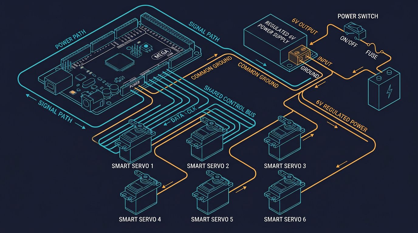
Most robot-arm failures blamed on firmware are actually power problems. The ESP32 operates at 3.3 V logic, while hobby servos often require 4.8–6 V and can draw several amps during startup or a stall. Never power a bank of servos from the ESP32 3.3 V pin. Use a regulated supply sized for the combined peak current, a separate buck converter for the controller, and a common ground between the controller and servo signal circuitry.
- Place a fuse or resettable protection device near the actuator supply.
- Use short, appropriately sized power and ground conductors; route high-current servo return paths away from sensitive analog sensors.
- Add bulk capacitance at the servo distribution point and local decoupling at the ESP32. Capacitors reduce transients; they do not replace a correctly sized supply.
- Check whether a servo signal accepts 3.3 V HIGH. If it does not, use a suitable level shifter or driver.
- Keep the USB ground and motor supply arrangement intentional to avoid ground loops and unexpected current paths.
PWM and servo timing
Many hobby servos use a repeating pulse around 50 Hz, with a pulse width commonly near 1,000–2,000 microseconds. Those values are not universal: some servos accept a wider range and some digital actuators use a completely different serial protocol. Start with the manufacturer’s limits and test one joint without a load. Driving a servo beyond its mechanical range can damage gears, overheat the motor or create an unsafe movement.
On Arduino-ESP32, the LEDC peripheral generates PWM without busy-waiting in the main loop. Use a defined update rate, constrain every target, and move gradually instead of jumping from one angle to another. A ramp improves mechanical behavior but does not provide torque control, collision detection or a safety rating. For six joints, a dedicated PWM expander or smart-servo bus can simplify wiring, but it still needs a correctly designed power system.
Working Arduino example: one controlled servo
The following example targets the Arduino-ESP32 core and uses LEDC. It deliberately starts at a conservative angle, constrains the command and updates without delay(). Confirm the LEDC API for the exact Arduino-ESP32 version used by your project; board packages can change peripheral APIs.
#include <Arduino.h>

constexpr uint8_t SERVO_PIN = 18;
constexpr uint32_t PWM_FREQUENCY = 50;
constexpr uint8_t PWM_RESOLUTION = 16;
constexpr uint16_t MIN_US = 1000;
constexpr uint16_t MAX_US = 2000;
constexpr uint32_t UPDATE_MS = 20;

uint32_t lastUpdate = 0;
int targetAngle = 90;
int currentAngle = 90;

uint32_t microsecondsToDuty(uint16_t pulseUs) {
  const uint32_t periodUs = 1000000UL / PWM_FREQUENCY;
  const uint32_t maxDuty = (1UL << PWM_RESOLUTION) - 1UL;
  return (static_cast<uint32_t>(pulseUs) * maxDuty) / periodUs;
}

void writeServoAngle(int angle) {
  angle = constrain(angle, 0, 180);
  const uint16_t pulseUs = map(angle, 0, 180, MIN_US, MAX_US);
  ledcWrite(SERVO_PIN, microsecondsToDuty(pulseUs));
}

void setup() {
  Serial.begin(115200);
  ledcAttach(SERVO_PIN, PWM_FREQUENCY, PWM_RESOLUTION);
  writeServoAngle(currentAngle);
}

void loop() {
  const uint32_t now = millis();
  if (now - lastUpdate >= UPDATE_MS) {
    lastUpdate = now;
    if (currentAngle < targetAngle) ++currentAngle;
    if (currentAngle > targetAngle) --currentAngle;
    writeServoAngle(currentAngle);
  }
}
For a production project, add command validation, a communication timeout, joint calibration values, a watchdog strategy and a hardware enable input. Before adding six axes, test the power rail with an oscilloscope or logger during simultaneous acceleration and verify that the controller resets neither from brownout nor electromagnetic interference.
Wi-Fi and Bluetooth: useful, but not deterministic
Wi-Fi is excellent for configuration pages, telemetry, firmware updates and non-critical remote commands. It is a poor substitute for a hardwired stop or deterministic motion bus. Radio interference, access-point roaming, retransmissions and task scheduling can create variable latency. Keep the motion loop local, reject stale packets, use sequence numbers and require a fresh heartbeat before accepting new targets. If the heartbeat expires, transition to a defined safe state.
BLE is useful for commissioning from a phone, while Wi-Fi can expose a local dashboard. Protect any control endpoint with authentication and network isolation. Do not expose an actuator-control web server directly to the public internet. For industrial integration, RS-485, CAN, Ethernet or a certified PLC interface may be more appropriate than a wireless link.
Safety and commissioning checklist
- Remove the tool or use a low-energy test fixture during initial setup.
- Set conservative software joint limits below the mechanical stops.
- Verify the direction of every joint at low speed, one axis at a time.
- Test loss of Wi-Fi, serial cable, encoder signal and controller reset.
- Test the physical emergency stop and confirm actuator energy is actually removed.
- Measure idle and stall current; do not infer supply requirements from nominal current alone.
- Record firmware, board revision, servo model, calibration offsets and supply voltage.
For a workplace installation, perform a documented risk assessment and follow the applicable machinery and robot-safety requirements in your jurisdiction. An ESP32 prototype should not be represented as compliant merely because it moves accurately.
Troubleshooting table
| Symptom | Likely cause | Check and correction |
|---|---|---|
| ESP32 resets when a joint moves | Voltage sag, noise or inadequate ground | Measure the 3.3 V rail during motion; separate supplies and improve grounding. |
| Servo jitters at rest | Unstable supply, noisy signal or unsuitable pulse range | Shorten signal wiring, add decoupling, verify pulse limits and test another supply. |
| Servo does not respond | Wrong pin, missing common ground or incompatible logic level | Verify pin mapping, ground continuity and the actuator’s signal threshold. |
| Motion pauses over Wi-Fi | Blocking networking code or radio latency | Use non-blocking tasks, local motion generation and a timeout for stale commands. |
| Joint hits its stop | Bad calibration or missing software limit | Reduce the range, calibrate neutral position and add an independent limit sensor. |
Recommended next steps
After the single-joint test, build the system incrementally. The Arduino robot arm tutorial provides a useful beginner path; compare transmission options in belt drive vs. gear drive; and review inverse kinematics for robot arms before implementing coordinated motion. For a broader design overview, see the complete 6-DOF robot arm guide.
Frequently asked questions
Can an ESP32 control six servos?
Yes, it can generate several PWM channels, but the practical answer depends on the actuator type, current supply, update timing, feedback and safety requirements. A PWM expander or smart-servo bus may be cleaner for a six-axis arm.
Can I power servos from the ESP32 board?
No. Use a separate regulated actuator supply and connect its ground to the ESP32 signal ground. The board’s regulator and USB connection are not intended to supply a multi-servo load.
Is Wi-Fi safe for robot-arm control?
Wi-Fi can carry monitoring or non-critical commands, but it should not be the only safety mechanism or the sole basis for deterministic motion. Use local limits, timeouts and a separate hardware safety chain.
Which ESP32 board should I choose?
Choose a well-supported board with the required GPIO, PWM, communication peripherals and 3.3 V logic. Confirm the exact chip family and Arduino core version because ESP32-WROOM-32, ESP32-S3 and ESP32-C3 are not interchangeable in every project.
Primary sources and further reading
These references support the general engineering concepts in this guide. Ratings and limits shown must be confirmed against documentation for your exact configuration.
Links checked: August 5, 2026.