What this guide covers
The short answer: when should you use carbon fiber?
Carbon-fiber composite parts are most useful when reducing moving mass improves the robot's torque demand, acceleration, vibration or energy use. A hollow carbon-fiber tube can be an excellent forearm or upper-arm link because material can be placed far from the neutral axis, increasing bending stiffness without adding as much mass as a solid metal link.
Carbon fiber is not automatically the best choice for every component. A joint housing with concentrated fasteners, impact exposure or complex machining may be easier to make from aluminum. A composite link also needs reliable end fittings, because the joint often fails at the insert or bond rather than in the middle of the laminate.
Choose carbon fiber after identifying the load path. If the part is primarily in bending, tube geometry and second moment of area matter. If it sees torsion, the laminate needs suitable off-axis plies and a closed section. If it is exposed to impact, abrasion, heat or repeated fatigue, validate the complete part rather than using a coupon value as a guarantee.
What carbon-fiber composites actually provide
Carbon fiber is anisotropic: it is strongest and stiffest along the fiber direction, while transverse and through-thickness properties come mainly from the resin and the interaction between plies. A datasheet value for a unidirectional lamina is not the rating of a finished robot link.
- Specific stiffness: a well-designed laminate can deliver high stiffness at relatively low mass.
- Specific strength: useful when the fibers are aligned with the main tensile load.
- Low thermal expansion: the fiber direction can be dimensionally stable, while the laminate still responds to temperature through resin and layup.
- Fatigue behavior: composites can perform well, but damage accumulation, joints and manufacturing defects must be evaluated.
- Vibration response: the structure, resin, interfaces and boundary conditions determine damping; carbon fiber is not automatically more damped than aluminum.
The useful engineering question is not "How strong is carbon fiber?" It is "What are the stiffness, strength, fatigue and failure properties of this laminate, in this geometry, with these joints, under this load spectrum?" ASTM D3039 or ISO 527 testing can characterize a specimen, but a component design still needs its own analysis and validation.
Tubes, plates and molded links
Carbon-fiber tubes
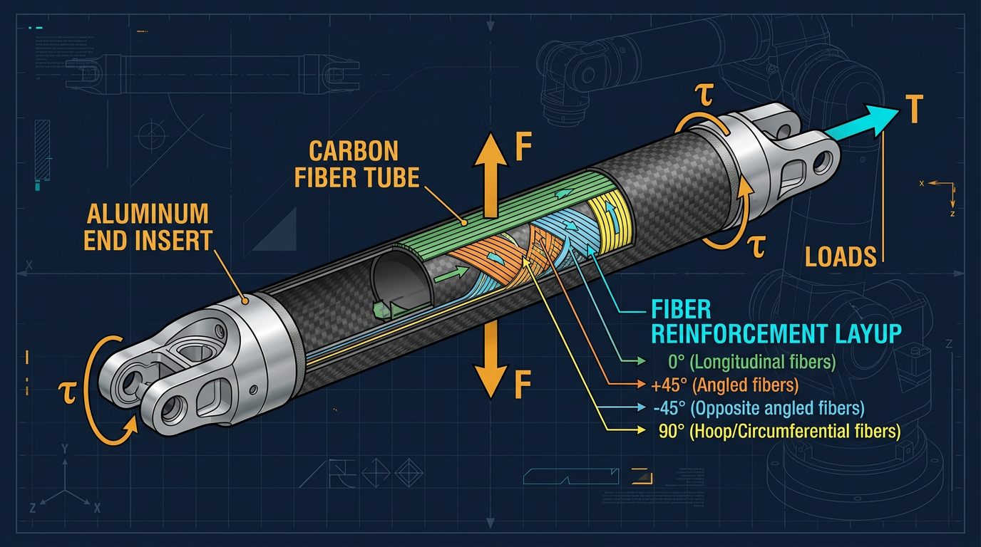
Round or rectangular tubes are efficient for beam-like arms. They place material around the section and can resist bending and torsion with a favorable stiffness-to-mass ratio. Pultruded tubes are consistent and convenient, but their fiber orientation may be optimized mainly for axial properties. Check whether the tube has enough off-axis reinforcement for torsion and local joint loads.
Flat laminates and plates
Flat carbon plates are useful for side cheeks, covers, sensor brackets and gussets. A plate can bend or buckle if it is too thin, and drilling a hole removes fibers and creates a stress concentration. Use edge distance, washers or bonded inserts and avoid clamping a thin laminate directly against a small bolt head.
Molded composite shells
A molded shell can integrate ribs, curves and mounting features. It may be efficient for a production arm, but tooling, surface control, cure consistency and inspection become more important. A visually smooth shell does not prove that the fiber placement or bond quality is correct.
| Form | Strength | Typical use | Primary risk |
|---|---|---|---|
| Tube | Efficient beam geometry | Upper arm and forearm links | Weak end fittings or local crushing |
| Plate | Easy to cut and assemble | Brackets, side plates and covers | Hole stress, buckling and delamination |
| Molded shell | Integrated geometry and ribs | Production housings and complex links | Tooling and process variability |
| Hybrid laminate | Tailored stiffness and impact response | High-load prototypes and tooling | Interface and cure compatibility |
Fiber orientation and laminate design
A laminate is built from plies with different orientations. A 0-degree ply carries load along the link axis, while ±45-degree plies contribute to shear and torsion. Ninety-degree plies support transverse loads and help stabilize the section. The correct balance depends on the load case; there is no universally correct "carbon-fiber layup."
For a beam with a dominant axial or bending load, begin with a load-path sketch and identify where tension and compression occur. For a torsion-dominant closed tube, off-axis plies are important. Balance and symmetry can reduce coupling between extension, bending and twisting, but the final laminate should be analyzed with appropriate composite-laminate methods.
Common design mistakes
- Using only unidirectional 0-degree tape in a joint that also sees torsion.
- Placing a fastener hole through a high-stress region without local reinforcement.
- Assuming a symmetric-looking part has a symmetric laminate.
- Ignoring free-edge delamination around a cut edge.
- Using a coupon tensile value as a bending or fatigue allowable.
- Forgetting that a metal insert can transfer a concentrated load into a small laminate area.
Joints, inserts and bonding
Most carbon-fiber robot-arm failures begin at an interface. A motor, bearing or gearbox applies a concentrated load, while the composite link distributes that load through a relatively thin wall. The joint should be designed to spread force with bonded sleeves, larger bearing seats, load-spreading washers, doublers or a properly engineered end fitting.
Bonded joints
Adhesive bonding can distribute load over a larger area than a small bolt. It requires compatible adhesive, controlled surface preparation, correct bond-line thickness, adequate overlap and protection from peel. Abrade and clean according to the adhesive and composite manufacturer's procedure; do not assume that wiping a glossy laminate with a random solvent creates a qualified surface.
Bolted joints
Bolts make inspection and replacement easier, but clamping can crush a laminate or create bearing failure around a hole. Use appropriate washers or inserts, control torque and provide sufficient edge distance. Drilling carbon fiber creates conductive dust and can damage the local fibers, so use proper extraction and finishing procedures.
Carbon fiber with aluminum
Carbon fiber is electrically conductive and can form a galvanic couple with aluminum in the presence of an electrolyte. Isolate the materials with a suitable coating, adhesive layer, sleeve or barrier washer, and prevent water from remaining at the interface. The joint must also account for different thermal expansion and the possibility of fretting.
Manufacturing methods and process control
Wet layup
Wet layup is accessible for prototypes but depends heavily on resin ratio, fiber wet-out, trapped air, consolidation pressure and cure conditions. A part can look acceptable while containing voids or resin-rich regions that reduce performance.
Vacuum bagging and infusion
Vacuum bagging improves consolidation and can reduce void content when the materials, leak rate and cure schedule are controlled. Resin infusion can produce consistent larger shells, but flow paths, resin viscosity, fiber compaction and cure temperature need process development.
Prepreg and out-of-autoclave systems
Prepreg systems provide controlled resin content and can improve repeatability, but they require freezer storage or a specified shelf-life workflow and controlled cure. Out-of-autoclave materials can be useful without an autoclave, but their datasheet values apply only under the published cure and test conditions.
Machining and finishing
Cutting cured composite produces abrasive conductive dust. Use local extraction, eye protection, respiratory protection appropriate to the material and a cleanup process that does not spread dust into electronics. Seal exposed edges and avoid leaving loose fibers where they can contact bearings, connectors or people.
Mass, stiffness and robot performance
Reducing link mass can reduce the torque required at the upstream joint. A simple static estimate is:
T = m × 9.81 × r
where m is mass and r is the perpendicular distance from the joint axis to the center of mass. Dynamic torque also includes acceleration, friction, payload and the inertia of the link. Moving mass closer to the joint can sometimes help more than changing material because the lever arm is reduced.
For bending stiffness, the first approximation is proportional to E × I, where E is the directional elastic modulus and I is the section's second moment of area. This is why a hollow tube can be efficient. A high-modulus material will not compensate for a poor section, weak joint or incorrect fiber orientation.
Validate the assembled link with a deflection test at the intended load. Measure displacement at the tool, not only at the link. Repeat the test after thermal cycling and after a representative motion cycle. Record mass, center of gravity, stiffness, resonance and any permanent set.
| Design question | What to measure | Why it matters |
|---|---|---|
| Will the link sag? | Static deflection under load | Changes tool position and calibration |
| Will it resonate? | Natural frequency and damping | Limits acceleration and control bandwidth |
| Will the joint survive? | Insert, bond and bearing loads | Interfaces often govern failure |
| Will it last? | Fatigue and cyclic inspection | One static test cannot prove life |
Inspection and validation
Use visual inspection, dimensional measurement and controlled load testing as a minimum for a prototype. For safety-relevant or production components, consider ultrasonic inspection, thermography, radiography or other non-destructive methods appropriate to the material and geometry. Document the laminate, cure, batch, operator, tooling and inspection result.
- Confirm dimensions, mass and center of gravity.
- Inspect edges, holes, inserts and bonded regions for cracks, voids or delamination.
- Apply a controlled proof load with the arm restrained and guarded.
- Measure deflection and check the return position after unloading.
- Cycle the joint at representative speed and inspect for damage or increasing play.
- Recalculate joint torque after the final link, fittings, cables and end-effector are installed.
Carbon-fiber part troubleshooting
| Symptom | Likely cause | Correction or check |
|---|---|---|
| Link is heavier than expected | Excess resin, extra plies or heavy inserts | Measure resin ratio and redesign the load path before removing material. |
| Visible crack near a bolt | Local bearing or clamp failure | Stop testing, inspect for delamination and redesign the insert or load spreader. |
| Joint becomes loose | Insert movement, bond failure or fretting | Disassemble safely and inspect the interface; do not simply retighten repeatedly. |
| Link twists under acceleration | Insufficient off-axis plies or open section | Measure torsional deflection and revise the laminate or section. |
| Carbon touches aluminum and corrodes | Galvanic coupling and moisture | Isolate the materials, seal the interface and inspect for hidden corrosion. |
| Surface looks good but stiffness is poor | Voids, resin-rich areas or wrong fiber orientation | Review process records and use suitable non-destructive inspection. |
Safety and responsible use
Carbon-fiber dust is conductive and irritating, and cured fragments can be sharp. Use suitable extraction, eye protection and respiratory controls while cutting or sanding. Keep dust away from motors, bearings, connectors and control electronics.
Do not use a composite link as a safety guard, lifting hook or human-contact component without professional design and validation. Production robot arms require guarding, emergency-stop functions, risk assessment, traceability and compliance with the applicable machinery requirements.
Final thoughts
Carbon fiber earns its place in a robot arm design when the load path is well understood and the mass savings translate into real gains in torque, acceleration or energy efficiency. It does not earn that place automatically just because it is lighter and stiffer on a datasheet. The parts of a carbon-fiber link most likely to fail — joints, inserts, bonded interfaces and drilled holes — are exactly the parts that generic fiber-direction data does not describe. Treat the laminate, the joint and the validation test as one design problem, not three separate afterthoughts, and you'll get a link that is both light and trustworthy.
Frequently asked questions
Why use carbon fiber for robot-arm links?
Carbon-fiber composites can provide high specific stiffness and low mass when the fibers are oriented along the principal loads. Lower link mass can reduce joint torque and inertia, but the result depends on laminate design, joints, manufacturing quality and validation.
Is carbon fiber stronger than aluminum for every robot part?
No. Carbon fiber is anisotropic and its properties depend on fiber direction, resin, laminate thickness, defects and loading mode. Aluminum is often easier to machine, inspect and join, and can be better for brackets, inserts or impact-prone parts.
Can carbon-fiber tubes be bonded to aluminum joints?
Yes, with a properly designed bonded or bonded-and-bolted joint. Address surface preparation, adhesive compatibility, load transfer, peel stress, galvanic corrosion, temperature and inspection.
Can a carbon-fiber robot arm be used in production?
It can be used after documented engineering validation, but a material datasheet alone is not enough. Production use may require fatigue testing, process control, inspection, guarding, traceability and compliance work.
Continue learning
For the complete mechanical system, read the 6-DOF Robot Arm Guide and compare belt and gear transmissions before finalizing the link design.