The End-Effector Is a System Component, Not an Accessory
Treating gripper selection as a catalog-browsing exercise — pick whatever has enough "holding force" on the spec sheet — skips the two calculations that actually determine whether a part stays gripped through a real motion cycle: the dynamic force during acceleration, and the actual contact geometry between the gripper and that specific part. A gripper rated for more force than the part's weight can still drop it if the part is smooth, the jaws contact it at a bad angle, or the robot accelerates hard enough that the required holding force spikes well above the static weight.
ISO 9409-1: The Mounting Standard That Determines What Physically Fits
Before force calculations even matter, the gripper has to bolt onto the robot. ISO 9409-1 standardizes the mechanical interface at the robot's wrist — a circular flange with a specific bolt circle diameter, center locating feature, and mounting hole pattern, categorized by size designations like Type 50, Type 63, or Type 100 (the number roughly corresponding to flange diameter in mm). A gripper built to match your robot's specified ISO 9409-1 flange type mounts directly; anything else needs a custom or off-the-shelf adapter plate, adding cost, potential runout error, and an extra point of mechanical failure.
Mechanical Grippers: The Friction Grip Force Calculation
A parallel-jaw or angular gripper holding a part by friction (rather than a form-fit around a feature) relies entirely on the clamping force generating enough friction to resist the part sliding out — including during acceleration, when the effective force required is higher than the part's static weight.
F_clamp = (m × (g + a) × SF) / (μ × n)

m   = mass of the part (kg)
g   = 9.81 m/s²
a   = peak acceleration the robot imparts on the part (m/s²)
SF  = safety factor (typically 2–4×, higher for critical or fragile parts)
μ   = coefficient of friction between jaw surface and part material
n   = number of jaw contact points (usually 2 for parallel grippers)
Worked example — a 1.5 kg smooth aluminum part, gripped by a 2-jaw parallel gripper with rubberized jaw pads (μ ≈ 0.4 against aluminum), moved by a robot with a peak acceleration of 8 m/s² during a fast pick, with a safety factor of 3:
F_clamp = (1.5 kg × (9.81 + 8) m/s² × 3) / (0.4 × 2)
F_clamp = (1.5 × 17.81 × 3) / 0.8
F_clamp = 80.1 / 0.8
F_clamp ≈ 100 N per jaw
Notice that acceleration nearly doubled the effective force term (17.81 vs. 9.81 for gravity alone) — a common mistake is sizing the gripper only against the part's static weight and ignoring the dynamic load entirely, which is fine at slow, careful speeds but fails the moment the cycle time gets optimized and the robot starts moving faster.
Form-Fit vs. Friction Grip
Where the part geometry allows it, gripping around a feature (a shoulder, a bore, a flange) so the gripper mechanically blocks the part from sliding out — rather than relying purely on friction — removes the dependency on μ almost entirely and is inherently more reliable for heavy or fast-moving parts. This is why gripper jaw design (custom fingers matching the part's geometry) is often worth the tooling cost over a generic flat jaw relying on friction alone.
Vacuum Grippers: Sizing by Contact Area and Vacuum Level
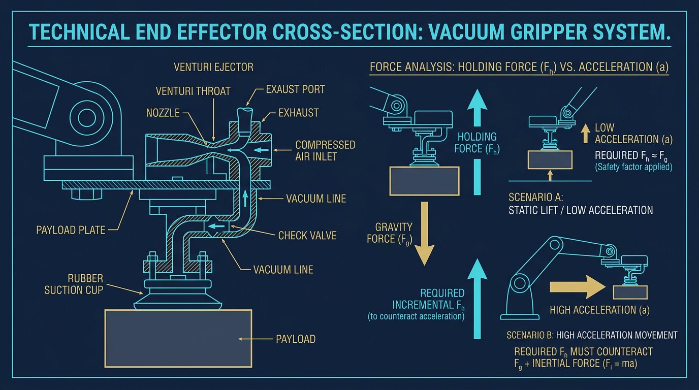
A vacuum cup's lifting capacity is a direct function of the pressure differential across the cup and the cup's effective sealed contact area — not a fixed number that transfers between applications:
F_cup = P × A

P = vacuum level, as a pressure differential (Pa or kPa)
A = effective sealed contact area of the cup (m²)

Number of cups required:
n_cups = (Total part weight × SF) / F_cup   [round up]
Worked example — lifting a 4 kg flat sheet metal part with round vacuum cups of 40mm diameter, using a vacuum level of 60 kPa (a common practical level, well below full vacuum for reliable industrial use), with a safety factor of 4x for a fast horizontal transfer move:
Cup radius = 20mm = 0.02m
Cup area A = π × r² = π × (0.02)² ≈ 0.001257 m²

F_cup = 60,000 Pa × 0.001257 m² ≈ 75.4 N per cup

Part weight force = 4 kg × 9.81 m/s² ≈ 39.2 N

n_cups = (39.2 N × 4) / 75.4 N ≈ 2.08 → round up to 3 cups minimum
The safety factor here matters more than in mechanical gripping because a vacuum seal failure is often silent until the part is already dropped — there's no gradual slip warning the way there can be with a friction grip losing traction. Porous, rough, or curved surfaces also reduce the effective sealed area below the cup's nominal geometric area, which is why manufacturer datasheets for cups intended for cardboard or textured surfaces often specify a lower effective lifting force than the raw geometric calculation would suggest.
Magnetic Grippers: When Friction and Vacuum Both Fail
For ferrous metal parts with irregular, porous, or oily surfaces where vacuum seals struggle and friction grip geometry is impractical, electropermanent or electromagnetic grippers hold by magnetic attraction across an air gap. Holding force here depends on the magnet's rated force at a given air gap distance and the part's material and thickness — a magnet rated for a given force against thick mild steel will underperform significantly against thin sheet stock or lower-permeability alloys. As with vacuum, manufacturer-rated holding force should be treated as a best-case number under ideal contact, not a guarantee for your specific part material.
Comparing the Three Primary Gripping Principles
| Principle | Best Suited For | Key Failure Mode | Sizing Depends On |
|---|---|---|---|
| Mechanical (friction/form-fit) | Irregular shapes, assembly, parts with graspable features | Slip under dynamic load if μ overestimated | Clamping force, friction coefficient, jaw geometry |
| Vacuum | Flat, smooth, non-porous surfaces (sheet metal, glass, cardboard, boxes) | Seal failure on porous/textured surfaces or leaks | Vacuum level, effective contact area, number of cups |
| Magnetic | Ferrous metal parts, especially thick/flat stock | Reduced force on thin or low-permeability material | Air gap, material thickness/permeability |
Payload and Center of Gravity: What Adding a Gripper Actually Costs You
A robot's published payload rating includes the end-effector's own mass — it is not additional capacity on top of the gripper's weight. A robot rated for 10 kg carrying a 2.2 kg gripper has 7.8 kg of genuine capacity left for the workpiece, fixtures, and any cable/hose weight hanging off the tool.
Equally important and more often overlooked: an asymmetric gripper shifts the combined payload's center of gravity away from the wrist's mounting axis. Most robot controllers require this offset (as X/Y/Z distance from the flange center, plus the combined mass) to be entered into the controller's tool/payload configuration — this isn't optional bookkeeping. An unaccounted-for offset center of gravity causes the controller's dynamic model to underestimate the actual torque and momentum the wrist and forearm joints experience during acceleration, which can trigger unexpected overload faults, degrade path accuracy, or in more severe cases contribute to premature joint wear.
Quick-Change Tool Couplers
For cells running multiple end-effectors on one robot (different grippers for different SKUs, or a gripper plus a screwdriving/dispensing tool), a robotic tool changer sits between the ISO 9409-1 flange and the actual tool, allowing automatic tool swaps mid-cycle. These couplers add their own weight and length to the payload/CoG calculation above, and typically carry their own rated payload and moment capacity that must exceed the combined gripper-plus-part load — the tool changer itself can become the limiting factor in the chain if undersized.
Common Selection Mistakes
- Sizing gripping force against static weight only, ignoring the acceleration term — fine at slow speed, fails once cycle time gets optimized.
- Using a manufacturer's published friction coefficient without verifying it against your actual part surface and jaw material — surface finish and contamination change μ meaningfully from generic reference tables.
- Treating vacuum cup lifting force as fixed regardless of surface texture, when porous or curved surfaces reduce effective sealed area below the datasheet's ideal-case number.
- Forgetting to declare the gripper's mass and center-of-gravity offset in the robot controller — leads to inaccurate dynamic compensation and possible overload faults.
- Choosing a mounting interface incompatible with the robot's actual wrist flange, discovered only after the gripper arrives and doesn't bolt on.
"A gripper's datasheet tells you what it can hold under ideal, static, lab conditions. Your specific part's surface, your robot's actual acceleration profile, and your safety factor are what tell you whether it'll still be holding on halfway through the cycle."— Robotics Engineering, Tooling & Mechanical Design Editorial Notes
Sources and Further Reading
- ISO 9409-1 — Manipulating industrial robots: Mechanical interfaces, Part 1: Plates. Defines the standardized wrist flange dimensions referenced throughout this article.
- Schunk — mechanical gripper application guides and jaw design references.
- Piab and Schmalz — vacuum gripper sizing guides and cup selection charts referenced for the vacuum calculation methodology.
- Robotiq and OnRobot — collaborative gripper and quick-change tool coupler documentation.
Force and sizing calculations in this article use standard mechanical engineering formulas; actual values (friction coefficients, vacuum levels, safety factors) must be determined for your specific part, gripper, and application rather than assumed from the illustrative examples shown.
How do I calculate the gripping force needed for a mechanical gripper?
For a friction-based grip, F = (m × (g + a) × SF) / (μ × n), where m is the part's mass, a is the peak acceleration, SF is a safety factor (typically 2-4x), μ is the friction coefficient, and n is the number of jaw contact points. Higher acceleration and lower friction both increase the required clamping force significantly.
How many vacuum cups do I need to lift a given weight?
Calculate a single cup's lifting force as vacuum level multiplied by effective contact area, then divide the total part weight (with a safety factor of 2x for vertical lifts or 4x+ for horizontal/dynamic moves) by that value to get the minimum number of cups, rounding up.
What is ISO 9409-1 and why does it matter for end-effector selection?
ISO 9409-1 defines standardized mechanical interface dimensions for robot wrist mounting flanges. A gripper matching your robot's specified flange type bolts on directly without a custom adapter plate.
Does the end-effector's weight actually reduce the robot's usable payload?
Yes, directly. A robot's rated payload includes the end-effector's own weight — a 10kg-rated robot carrying a 2kg gripper only has 8kg left for the workpiece. An off-center gripper also requires declaring the shifted center of gravity to the controller so it can correctly compensate for the resulting moment load.