Three Servo Categories, Not One "Smart Servo" Market
"Servo motor" gets used loosely across three genuinely different technologies, and confusing them is a common source of failed builds. Understanding the actual difference matters more than any spec sheet number.
1. Standard PWM Hobby Servos
The classic RC-style servo (like the widely used MG996R or SG90) takes a single pulse-width-modulated signal — typically a pulse between 1000 and 2000 microseconds repeated every 20ms, where pulse width maps to target angle. Internally it has its own small feedback loop (usually a potentiometer) driving a DC motor toward that target, but the controller never receives any position feedback back. You command an angle and hope it got there. Each servo needs its own dedicated signal wire.
2. Digital Serial "Smart" Bus Servos
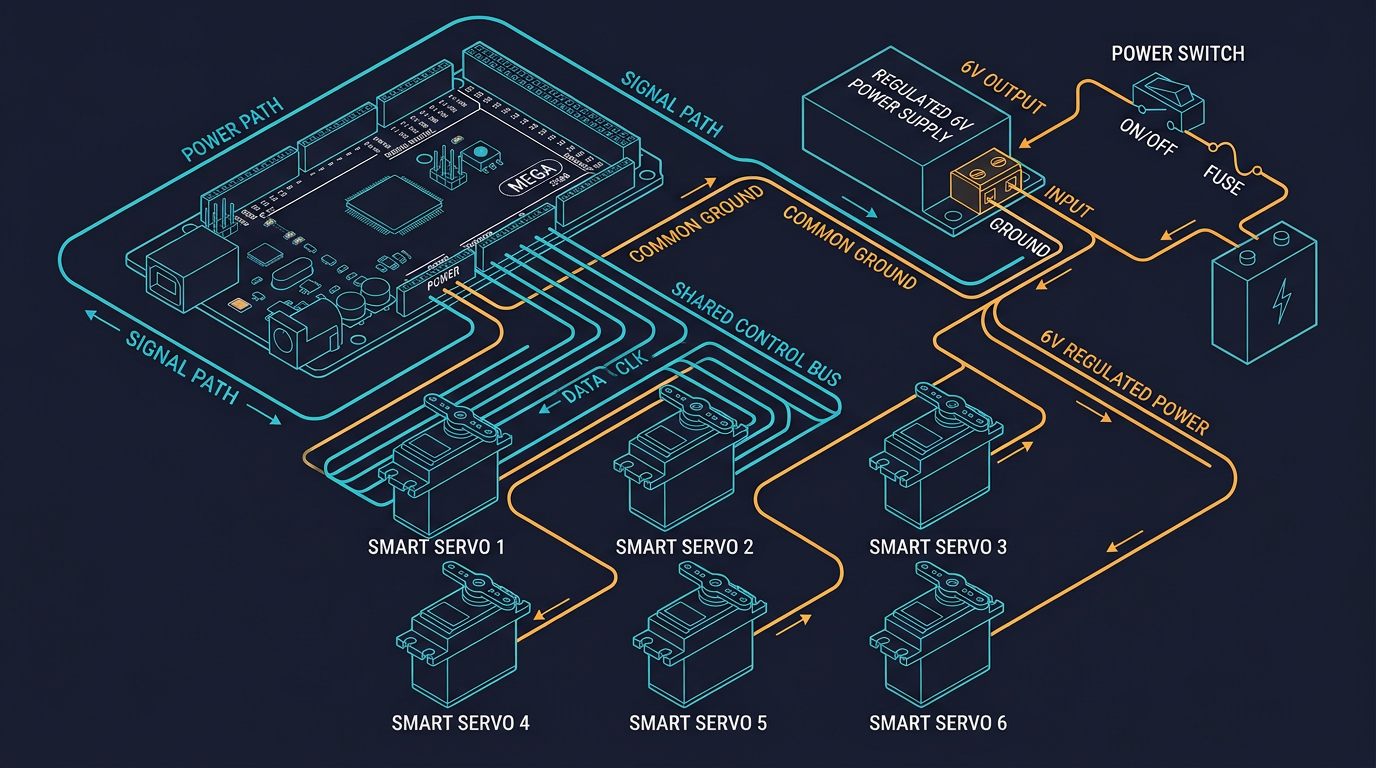
Bus servos (Dynamixel from Robotis, the Feetech STS/SCS series, Hiwonder LX/HTS series) replace the PWM wire with a digital serial protocol. Multiple servos share the same two-wire bus, each with a unique ID, and the controller sends structured packets rather than raw pulses. Critically, these servos **report back** — actual position, load, voltage, and often temperature — turning open-loop control into closed-loop control at the system level. This is what actually justifies the "smart" name.
3. Industrial AC/BLDC Servo Drives
What industrial robot arms use isn't a "servo" in the hobbyist sense at all — it's a brushless or AC motor paired with a separate high-bandwidth servo drive running a dedicated PID loop (position/velocity/current cascaded control) at kHz update rates, closed over an absolute encoder via protocols like EtherCAT or CANopen. These systems are a different scale of cost and complexity, and are covered separately in our joint encoder guide and harmonic drive review — this article focuses on the PWM and bus servo categories relevant to desktop and educational 6-DOF arms.
Calculating the Torque You Actually Need
The single most common design mistake in DIY arms is picking a servo based on price or brand reputation rather than a real torque calculation. The formula is straightforward static analysis:
Required Torque = (Payload weight + Sum of link weights beyond this joint)
                   × gravitational acceleration (9.81 m/s²)
                   × horizontal lever arm length (worst case: fully extended)
                   × safety factor (1.5–2.0)
Worked example — shoulder joint of a small desktop arm: Suppose the arm carries a 500g payload, the forearm and wrist assembly beyond the shoulder weighs 400g combined, and the arm's horizontal reach at full extension is 250mm (0.25m).
Total mass  = 0.5 kg (payload) + 0.4 kg (links) = 0.9 kg
Force       = 0.9 kg × 9.81 m/s² = 8.83 N
Torque      = 8.83 N × 0.25 m = 2.21 N·m
With 1.75x safety factor = 2.21 × 1.75 ≈ 3.87 N·m ≈ 39.5 kg·cm
That result — roughly 40 kg·cm — tells you immediately that a small 9g micro servo (rated around 1.5–2 kg·cm) is nowhere close to sufficient for this joint, while a mid-range digital bus servo rated 30–35 kg·cm would be marginal without the safety factor and undersized with it. This calculation should be repeated for every joint using its own downstream weight and lever arm — the base and shoulder almost always need dramatically more torque than the wrist.
Controlling a PWM Servo: The Simple Case
For PWM servos, Arduino's built-in Servo library handles pulse generation directly — no protocol to implement:
#include <Servo.h>

Servo shoulderServo;

void setup() {
    shoulderServo.attach(9);      // PWM-capable pin
    shoulderServo.write(90);      // center position, degrees
}

void loop() {
    shoulderServo.write(45);      // move to 45 degrees
    delay(1000);
    shoulderServo.write(135);
    delay(1000);
}
Controlling a Smart Bus Servo: Building the Protocol Packet
Bus servos from Feetech and similar manufacturers use a packet structure over half-duplex serial (single wire, or TX/RX tied together with a level shifter). The general structure looks like this:
[0xFF] [0xFF] [ID] [Length] [Instruction] [Param 1]...[Param N] [Checksum]

Checksum = (~(ID + Length + Instruction + Param1 + ... + ParamN)) & 0xFF
Here's a simplified example implementing a "move to position" command in the style of Feetech's SCS/STS protocol — always confirm your specific servo model's register map in its datasheet, since address offsets vary between series:
// Simplified move-to-position packet, Feetech-style protocol
// Connect bus servo signal line to a hardware or software serial port

void moveServo(uint8_t id, uint16_t position, uint16_t timeMs) {
    uint8_t params[] = {
        42,                              // register address: goal position (check datasheet)
        (uint8_t)(position & 0xFF),      // position low byte
        (uint8_t)(position >> 8),        // position high byte
        (uint8_t)(timeMs & 0xFF),        // move time low byte
        (uint8_t)(timeMs >> 8)           // move time high byte
    };
    uint8_t instruction = 0x03;         // WRITE instruction
    uint8_t length = sizeof(params) + 2;

    uint16_t sum = id + length + instruction;
    for (uint8_t p : params) sum += p;
    uint8_t checksum = ~(sum & 0xFF);

    Serial1.write(0xFF); Serial1.write(0xFF);
    Serial1.write(id);
    Serial1.write(length);
    Serial1.write(instruction);
    for (uint8_t p : params) Serial1.write(p);
    Serial1.write(checksum);
}

void setup() {
    Serial1.begin(1000000);   // typical bus servo baud rate — confirm per model
}

void loop() {
    moveServo(1, 512, 800);   // servo ID 1, mid-position, 800ms move time
    delay(1000);
    moveServo(1, 800, 800);
    delay(1000);
}
Reading position feedback follows the same packet structure with a READ instruction (typically 0x02) instead of WRITE, and parsing the servo's response packet. In practice, most projects use the manufacturer's SDK (Feetech's SCServo library, or the Dynamixel SDK for Robotis servos) rather than hand-building packets — the manual protocol above is shown so you understand what those libraries are doing underneath, which matters when debugging communication errors.
Published Specifications: What's Actually on the Datasheet
These figures come from publicly available manufacturer datasheets for commonly used models in each category — always confirm against the current datasheet for your exact model and voltage, since torque scales with supply voltage.
| Model / Type | Stall Torque | Feedback | Control Interface | Typical Use |
|---|---|---|---|---|
| Generic 9g micro (SG90-class) | ~1.6 kg·cm @ 4.8V | None (open-loop) | PWM | Grippers, light wrist axes |
| MG996R-class PWM servo | ~9.4–11 kg·cm @ 4.8–6V | None (open-loop) | PWM | Small desktop arm joints |
| Dynamixel AX-12A | ~1.5 N·m (~15 kg·cm) @ 12V | Position, load, temp, voltage | TTL serial bus, daisy-chain | Educational/research arms |
| Feetech STS3215 | ~30 kg·cm @ 12V (variants vary) | Position, load, temp, voltage | Serial bus, daisy-chain | DIY 6-DOF arm base/shoulder joints |
| Hiwonder LX-16A | ~17 kg·cm @ 7.4V | Position (ADC), voltage | Serial bus, daisy-chain | Mid-range DIY arms, hexapods |
Note the resolution difference too: PWM servos typically resolve to roughly 0.5–1° depending on the receiving library's pulse timing precision, while bus servos commonly use 10-12 bit position sensing (1024–4096 steps across their range), giving resolution around 0.088–0.3° per step — a meaningful difference for tasks requiring fine positioning.
Choosing the Right Type Per Joint
- Base and shoulder (J1-J2): Highest torque demand due to the longest lever arm and heaviest downstream mass. This is where undersized servos fail first — prioritize bus servos with published continuous (not just stall) torque ratings, or accept a reduced practical payload.
- Elbow (J3): Still significant torque, though less than the shoulder. Bus servos remain the safer choice for anything beyond very light educational builds.
- Wrist assembly (J4-J6): Lower torque requirement since these joints only move the end-effector and its immediate load, not the rest of the arm's mass. This is where smaller PWM or lower-torque bus servos are commonly acceptable, and where compact size matters more than raw torque.
- Any joint used in a closed-loop or force-sensitive application: Bus servos are the only sensible choice, since PWM servos cannot report actual position or load back to the controller — you're flying blind on whether the commanded position was actually achieved.
Common Mistakes That Show Up After the Build Is "Finished"
- Sizing servos by price bracket instead of the torque calculation above — the most frequent cause of an arm that droops or stalls under its rated payload.
- Daisy-chaining bus servos without setting unique IDs first — every bus servo ships from the factory with the same default ID, and they must be individually connected and reassigned before wiring them together on a shared bus, or commands will be received by all of them simultaneously.
- Ignoring combined stall current when sizing the power supply — six servos each drawing 1-2A at stall need a supply rated for the sum, not the average, since worst-case moves can demand near-simultaneous peak current.
- Mixing PWM and bus servos without separating their grounds and signal logic properly — bus servos often run at different logic/communication voltage than a PWM signal pin, and improper level shifting is a common source of intermittent communication errors.
"A servo's spec sheet tells you what it can do for an instant at stall. Your arm's design has to account for what it can sustain — that gap is where most DIY builds run into trouble."— Robotics Engineering, Motion Control Editorial Notes
Sources and Further Reading
- Robotis Dynamixel e-Manual — official specifications and protocol documentation for the Dynamixel AX and X series bus servos.
- Feetech — datasheets and protocol references for the SCS/STS serial bus servo series.
- Hiwonder — LX/HTS series bus servo documentation.
- Arduino
Servo.hLibrary Reference — official documentation for PWM servo control on Arduino-compatible boards.
Torque and resolution figures above are drawn from publicly published manufacturer specifications at the time of writing and vary by supply voltage and specific model revision. Always verify against the current datasheet for the exact part you're purchasing.
What's the actual difference between a hobby PWM servo and a smart bus servo?
A PWM servo takes a single analog pulse-width signal per unit, has no position feedback to the controller, and needs one dedicated signal wire per servo. A smart bus servo communicates over a shared serial line using a digital packet protocol, reports back its actual position, load, temperature, and voltage, and multiple units can be daisy-chained on the same two wires using unique IDs.
How do I calculate how much torque a servo needs for a robot arm joint?
Multiply the total weight the joint must lift (payload plus the weight of every link beyond that joint) by gravitational acceleration and by the horizontal lever arm distance at full extension, then multiply by a safety factor of roughly 1.5-2x to account for dynamic loads during acceleration.
Can I power six servos directly from an Arduino's 5V pin?
No. The onboard regulator supplies well under 1A, while six servos moving under load can draw several amps combined. Use a separate power supply sized for combined stall current, sharing only ground with the microcontroller.
Why do smart bus servos use a checksum in their communication protocol?
The checksum lets the receiving servo verify the command packet wasn't corrupted during transmission over the shared bus. Since one line carries commands to many servos with different IDs, catching a corrupted packet's ID before acting on it prevents the wrong servo from executing an unintended movement.