Why Joint Position Feedback Is the Foundation of Robot Arm Precision
A 6-axis robot arm doesn't know where its tool center point is in space — it calculates it. The controller reads the angle of each of the six joints, runs that data through forward kinematics, and derives the position of the end-effector. If a single joint's angle reading is wrong by even a fraction of a degree, that error compounds through the kinematic chain and shows up as a positioning mistake at the tool, often magnified several times over by the length of the downstream links.
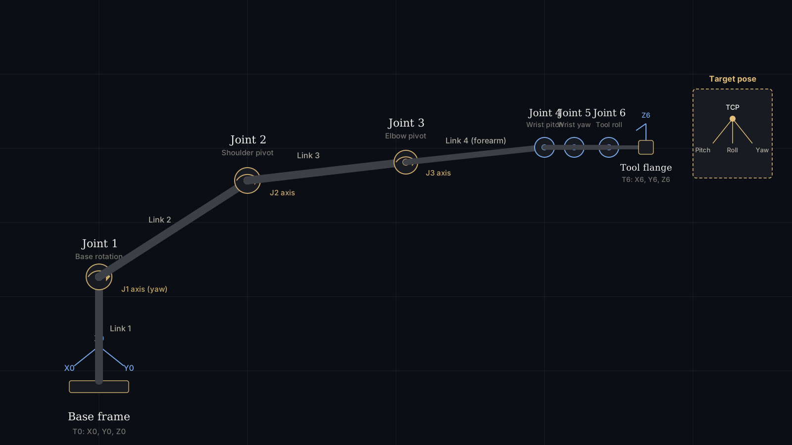
This is why the encoder — not the motor, not the gearbox — is often the component that ultimately limits a robot's repeatability. Two arms with identical motors and identical harmonic drives can have very different repeatability specs purely because of encoder resolution and mounting quality.
Absolute Encoders: Knowing Position Without Moving
An absolute encoder outputs a unique digital code for every possible shaft position — the moment power is applied, the controller can read that code and know the exact angle, with no movement required. This is done with a coded disk (optical types) or a coded magnetic pattern, read in parallel across multiple tracks, each representing one bit of the position word.
A 19-bit single-turn absolute encoder divides one full rotation into 219 = 524,288 unique positions. That works out to:
That resolution exists at the motor shaft. On a joint using a 100:1 harmonic drive, the encoder is almost always mounted before the reduction stage, so this resolution is preserved (and effectively amplified) at the output — but the achievable real-world accuracy is then governed by the gearbox's own backlash and torsional stiffness, not by the encoder.
Single-Turn vs. Multi-Turn Absolute
A single-turn absolute encoder only knows the angle within one revolution — it has no memory of how many full turns the shaft has made. That's a problem for joints like the robot's base (J1) or wrist roll (J6), which may rotate through several full turns during a motion sequence. A multi-turn absolute encoder solves this by adding a turn counter, traditionally powered by a backup battery or gear-train mechanical counter, and increasingly today by energy-harvesting technologies (Wiegand wire pulses or self-powered magnetic sensors) that don't require any battery at all — a meaningful reliability advantage, since a dead backup battery on a multi-turn encoder means the robot loses its position reference and must be re-homed.
Incremental Encoders: Fast, Cheap, But They Need to Be Told Where Home Is
An incremental encoder doesn't output a position — it outputs pulses as the shaft rotates. A typical optical incremental encoder produces two square-wave channels, A and B, offset 90° from each other (quadrature), plus a single index pulse (Z) once per revolution. A "2,500 PPR" (pulses per revolution) encoder generates 2,500 pulses per channel per turn.
The controller counts edges to track relative movement. Using both channels and detecting both rising and falling edges (x4 decoding), a 2,500 PPR encoder actually yields 10,000 countable states per revolution:
The catch: an incremental encoder has no idea what angle it's at when power is first applied — it only knows how much it has moved since power-on. That's why every robot using incremental encoders needs a homing routine at startup, moving each joint to a mechanical or optical reference (a home switch, or the Z-index pulse) before it can trust its position data. This adds startup time and is a real risk if a joint moves during a power loss and the home reference is lost — which is the main reason incremental encoders have been largely displaced by absolute types in commercial industrial arms, though they remain common and cost-effective in DIY and educational 6-DOF builds.
Magnetic Encoders: Contactless Sensing for Compact Joints
Magnetic encoders replace the optical disk-and-light-source pair with a small diametrically magnetized magnet mounted on the shaft and a stationary sensor IC positioned a fraction of a millimeter below it (typically 0.5–2 mm air gap). The sensor — built on AMR (anisotropic magnetoresistance), GMR (giant magnetoresistance), or Hall-array technology — measures the direction of the rotating magnetic field and converts that angle directly into a digital output, often over a simple SPI, PWM, or analog interface.
Because there's no physical contact and no optical path that can be blocked by dust or oil film, magnetic encoders tolerate the vibration, grease, and metal particulate common inside a robot's wrist and elbow joints far better than optical absolute encoders. They're also physically smaller and cheaper, which is why they've become the default choice for the compact wrist joints (J4–J6) on collaborative robots, and for nearly all DIY/educational 6-DOF arms using chips like the AS5048 or AS5600 family. The trade-off is generally lower maximum resolution (commonly 12–14 bit, or 4,096–16,384 counts/rev) and higher sensitivity to stray magnetic fields from nearby motor windings, which requires careful shielding and magnet placement.
Absolute vs. Incremental vs. Magnetic: Direct Comparison
| Property | Optical Absolute | Optical Incremental | Magnetic (AMR/Hall) |
|---|---|---|---|
| Position known at power-on | Yes, immediately | No — requires homing | Yes, immediately |
| Typical resolution | 17–24 bit (131K–16.7M counts/rev) | 500–10,000 PPR (up to 40,000 counts/rev with x4) | 10–14 bit (1,024–16,384 counts/rev) |
| Contamination resistance | Low — optical path can be blocked | Low | High — fully contactless |
| Multi-turn tracking | Yes (with battery or Wiegand backup) | No (unless paired with external counter) | Some models (via external magnet counting IC) |
| Relative cost | High | Low | Low–Medium |
| Typical placement on a 6-DOF arm | Base & shoulder joints (J1–J3) | DIY / low-cost educational arms | Wrist joints (J4–J6), collaborative robots |
Communication Buses: How Encoder Data Reaches the Controller
Raw encoder signals rarely travel far on their own — modern servo drives use digital bus protocols that combine position data, temperature, and diagnostics on a small number of wires. Understanding these matters when integrating third-party encoders or troubleshooting a joint fault.
| Protocol | Wiring | Typical Update Rate | Common Use |
|---|---|---|---|
| SSI (Synchronous Serial Interface) | 4 wires (clock + data, differential) | Up to ~2 Mbit/s | Legacy industrial absolute encoders |
| BiSS-C | 4 wires, open standard, SSI-compatible | Up to 10 Mbit/s | Modern absolute/incremental hybrid encoders |
| EnDat 2.2 | 4–6 wires (Heidenhain proprietary) | Up to 16 Mbit/s | High-end industrial servo axes |
| HIPERFACE DSL | 2 wires, shares motor power cable | Sufficient for real-time servo loops | Reduces cabling in compact joint assemblies |
| SPI / analog (raw) | 3–4 wires | MHz-range, direct microcontroller read | DIY arms with magnetic encoder ICs (AS5048, AS5600) |
The shift toward two-wire protocols like HIPERFACE DSL matters more than it might seem: every extra wire running through a 6-axis arm's internal cable harness is another point of fatigue failure as the wrist joints twist through their range of motion thousands of times per day. Fewer encoder wires generally means a longer service life for the arm's internal cabling.
Choosing the Right Encoder Per Joint
Commercial 6-axis arms rarely use identical encoders on all six joints — the requirements at the base differ meaningfully from the requirements at the wrist.
- J1 (base rotation): Often unlimited or near-unlimited rotation range. Requires a multi-turn absolute encoder, or an absolute encoder combined with a mechanical or software turn-counting strategy.
- J2–J3 (shoulder, elbow): Carry the highest structural loads and torque. Prioritize high single-turn resolution and robust sealing, since these joints see the most cumulative motion over the arm's duty cycle.
- J4–J6 (wrist assembly): Space is the constraint — these joints are physically smaller, which favors compact magnetic encoders. Contamination resistance also matters more here in welding or dispensing applications where the wrist is closest to the process.
This is also why encoder selection should never be evaluated in isolation from the gearbox: a harmonic drive's own hysteresis and backlash (commonly 1–3 arcminutes even on precision-grade units) often exceeds the angular error contributed by the encoder itself. Pairing a low-cost gearbox with a premium high-resolution encoder is a common over-engineering mistake in DIY builds.
Installation, Calibration and Homing in Practice
Regardless of encoder type, three practical factors determine whether the theoretical resolution translates into real accuracy:
- Concentricity of mounting: Optical encoders are sensitive to shaft runout; even 0.05 mm of radial misalignment can introduce measurable position error across a rotation. Magnetic encoders are more tolerant but still require the air gap between magnet and sensor IC to stay within the manufacturer's specified range across the joint's full temperature swing.
- EMI shielding: Encoder signal wires routed near motor phase cables can pick up electrical noise that corrupts position counts, especially with unshielded quadrature signals. Twisted-pair shielded cable and physical separation from power wiring are standard practice inside robot arm harnesses.
- Homing sequence design (incremental only): A typical homing routine moves the joint at reduced speed toward a limit switch, then reverses slowly until the encoder's Z-index pulse is detected, setting that point as the zero reference. Poorly tuned homing speed is a common source of repeatability complaints in DIY incremental-encoder builds.
Failure Modes Worth Knowing Before They Happen
- Battery-backed multi-turn encoders losing their backup battery — the encoder forgets its turn count and the robot must be manually re-referenced, sometimes requiring the arm to be moved to a known mechanical position.
- Magnetic encoder interference from nearby brushless motor fields — solved with magnetic shielding cans or increasing sensor-to-motor distance during mechanical design, not something that can be fixed in software after the fact.
- Optical encoder disk contamination from gearbox grease migration — the reason optical absolute encoders on industrial arms are typically sealed to IP54 or better at the joint.
- Connector and flex-cable fatigue at wrist joints that rotate continuously — a strong argument for two-wire bus protocols and generous service-loop cable routing.
"The encoder doesn't make the robot accurate — it makes the robot's own error visible and correctable. Everything downstream of the sensor, from gearbox backlash to structural flex, still has to be engineered around."— Robotics Engineering, Motion Control Editorial Notes
Sources and Further Reading
Technical background in this article draws on publicly available encoder application notes and industry standards, including:
- Heidenhain — application guides on EnDat 2.2 and absolute rotary encoder design.
- Renishaw — optical and magnetic encoder technology overviews.
- ams-OSRAM — datasheets for magnetic position sensor ICs (AS5048, AS5600 series) commonly used in compact and DIY robot joints.
- ISO 9409-1 — mechanical interface standard referenced for robot flange and joint mounting.
- IFR (International Federation of Robotics) — market and adoption context for industrial and collaborative robot arms.
Readers should confirm exact resolution, accuracy, and interface specifications against the current datasheet of the specific encoder model being evaluated, since figures vary by manufacturer and product generation.
What's the real difference between an absolute and an incremental encoder?
An absolute encoder reports a unique digital position code the instant it's powered on, so the robot knows exactly where each joint is without moving. An incremental encoder only outputs pulses as the shaft turns, so the controller must run a homing routine at every startup to establish a reference position.
Why do most modern 6-axis arms use absolute encoders instead of incremental ones?
Absolute encoders eliminate the need for homing after every power cycle, which matters in production lines where a robot may stop mid-cycle due to a power outage. Multi-turn absolute versions also track how many full rotations a joint has made, which is essential for joints without mechanical hard stops.
How does a magnetic encoder actually sense position?
A small diametrically magnetized magnet is mounted on the motor shaft. A stationary sensor chip below it measures the direction of the magnetic field as it rotates and converts that angle into a digital position value — with no physical contact, which is why magnetic encoders tolerate dust, oil, and vibration far better than optical ones.
Does gearbox ratio change what encoder resolution I need?
Yes. An encoder mounted on the motor shaft before a 100:1 reduction stage has its resolution effectively multiplied by 100 at the joint output — but backlash and torsional compliance in the gearbox, not the encoder, usually become the limiting factor for real positional accuracy.
Related Reading
- Harmonic Drive Review for 6-DOF Robot Arms: Precision & Backlash
- Force and Torque Sensors for 6-DOF Robot Arms: Integration & Calibration
- Robot Arm Cable Management: Internal Routing, Slip Rings & Protective Sleeves
- ROS 2 Control Architecture for 6-DOF Robot Arms
- The Complete 6-DOF Robot Arm Guide (2026)