What Problem ros2_control Actually Solves
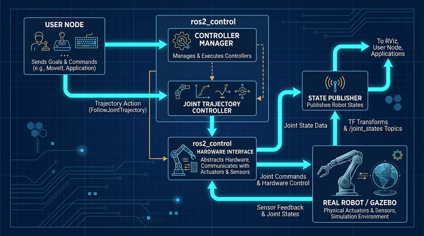
Before ros2_control existed as a standard, every ROS robot driver reinvented the same wheel: reading joint encoders, running a control loop, handling trajectory interpolation, and exposing that to the rest of the software stack — all custom, all slightly incompatible with the next robot's driver. ros2_control's core idea is separation of concerns: hardware-specific code (talking to your actual motors) is isolated into a small, swappable component, while control logic (trajectory following, PID loops, gravity compensation) lives in reusable, hardware-agnostic controllers that work identically whether you're driving a simulated arm, a Dynamixel-based DIY arm, or an EtherCAT industrial servo system.
This matters practically: once you've written a correct hardware interface for your robot, you get access to the entire ecosystem of existing controllers (joint trajectory controller, forward position controller, admittance controller) and tools (MoveIt 2, rqt_joint_trajectory_controller, ros2_control's built-in diagnostics) without writing any of that logic yourself.
The Three Layers of the Architecture
- Hardware Interface — the plugin you write that talks to real (or simulated) actuators and sensors. It exposes standardized state interfaces (position, velocity, effort feedback) and accepts standardized command interfaces (position, velocity, or effort setpoints).
- Controller Manager — a ROS 2 node that loads your hardware interface, loads one or more controllers, and runs the update loop at a configured frequency, routing data between them.
- Controllers — hardware-agnostic algorithms (like
joint_trajectory_controller) that consume state interfaces and produce command interfaces to drive the robot toward a goal.
Step 1 — Declaring Hardware in URDF
ros2_control configuration starts in your robot's URDF/xacro description, inside a <ros2_control> tag that declares each joint's available interfaces:
<ros2_control name="SixDofArmSystem" type="system">
  <hardware>
    <plugin>my_robot_hardware/SixDofArmHardwareInterface</plugin>
    <param name="serial_port">/dev/ttyUSB0</param>
    <param name="baud_rate">1000000</param>
  </hardware>

  <joint name="joint_1">
    <command_interface name="position"/>
    <state_interface name="position"/>
    <state_interface name="velocity"/>
  </joint>
  <joint name="joint_2">
    <command_interface name="position"/>
    <state_interface name="position"/>
    <state_interface name="velocity"/>
  </joint>
  <!-- Repeat for joint_3 through joint_6 -->
</ros2_control>
The plugin tag references the C++ class you'll write in the next step — this is how the controller manager knows which hardware interface implementation to load for this robot.
Step 2 — Writing the Hardware Interface Plugin
The hardware interface is a C++ class inheriting from hardware_interface::SystemInterface. It implements four key lifecycle methods: reading current joint states, and writing commanded joint values. Here's a simplified but functionally accurate skeleton:
#include "hardware_interface/system_interface.hpp"

class SixDofArmHardwareInterface : public hardware_interface::SystemInterface {
public:
  hardware_interface::CallbackReturn on_init(
      const hardware_interface::HardwareInfo & info) override {
    // Parse URDF params (serial_port, baud_rate) and allocate joint buffers
    joint_positions_.resize(info.joints.size(), 0.0);
    joint_commands_.resize(info.joints.size(), 0.0);
    return hardware_interface::CallbackReturn::SUCCESS;
  }

  std::vector<hardware_interface::StateInterface> export_state_interfaces() override {
    std::vector<hardware_interface::StateInterface> state_interfaces;
    for (size_t i = 0; i < joint_positions_.size(); ++i) {
      state_interfaces.emplace_back(
        info_.joints[i].name, "position", &joint_positions_[i]);
    }
    return state_interfaces;
  }

  std::vector<hardware_interface::CommandInterface> export_command_interfaces() override {
    std::vector<hardware_interface::CommandInterface> command_interfaces;
    for (size_t i = 0; i < joint_commands_.size(); ++i) {
      command_interfaces.emplace_back(
        info_.joints[i].name, "position", &joint_commands_[i]);
    }
    return command_interfaces;
  }

  hardware_interface::return_type read(const rclcpp::Time &, const rclcpp::Duration &) override {
    // Poll real hardware (serial bus, EtherCAT, etc.) and update joint_positions_
    // e.g. readServoPositions(joint_positions_);
    return hardware_interface::return_type::OK;
  }

  hardware_interface::return_type write(const rclcpp::Time &, const rclcpp::Duration &) override {
    // Send joint_commands_ to real hardware
    // e.g. writeServoTargets(joint_commands_);
    return hardware_interface::return_type::OK;
  }

private:
  std::vector<double> joint_positions_;
  std::vector<double> joint_commands_;
};
The read() and write() methods are called at the controller manager's update rate — this is where you'd insert the actual serial protocol code (like the bus servo packet structure covered in our servo motor guide) or an EtherCAT process data exchange. Everything above this layer never needs to know which one you're using.
PLUGINLIB_EXPORT_CLASS macro call and a plugin XML description file so pluginlib can dynamically load your class by the name referenced in the URDF. Omitting this is one of the most common first-time build errors — the controller manager fails at runtime with a "plugin not found" error rather than a compile error.
Step 3 — Configuring Controllers via YAML
With the hardware interface in place, you configure which controllers to run in a YAML file loaded by the controller manager. A typical 6-DOF arm setup uses a joint_trajectory_controller for coordinated motion and a joint_state_broadcaster to publish current state:
controller_manager:
  ros__parameters:
    update_rate: 500  # Hz

    joint_state_broadcaster:
      type: joint_state_broadcaster/JointStateBroadcaster

    arm_trajectory_controller:
      type: joint_trajectory_controller/JointTrajectoryController

arm_trajectory_controller:
  ros__parameters:
    joints:
      - joint_1
      - joint_2
      - joint_3
      - joint_4
      - joint_5
      - joint_6
    command_interfaces:
      - position
    state_interfaces:
      - position
      - velocity
    constraints:
      goal_time: 0.5
      stopped_velocity_tolerance: 0.02
The update_rate here determines how frequently the controller manager calls your hardware interface's read()/write() methods — 500Hz is a common starting point for servo-based arms; industrial EtherCAT systems often run at 1kHz or higher. Setting this higher than your actual hardware can physically respond to just wastes CPU cycles without improving control quality.
Step 4 — Launching and Verifying
A launch file starts the controller manager with your URDF and controller YAML, then spawns the controllers:
Node(
    package="controller_manager",
    executable="ros2_control_node",
    parameters=[robot_description, controller_config_path],
    output="screen",
),
Node(
    package="controller_manager",
    executable="spawner",
    arguments=["joint_state_broadcaster"],
),
Node(
    package="controller_manager",
    executable="spawner",
    arguments=["arm_trajectory_controller"],
),
Once running, you can inspect and interact with the system directly from the command line — genuinely useful for debugging before writing any client code:
# List all loaded controllers and their state
ros2 control list_controllers

# List available hardware interfaces
ros2 control list_hardware_interfaces

# Echo current joint states being published
ros2 topic echo /joint_states
Connecting to MoveIt 2
ros2_control handles execution — actually moving the joints along a trajectory. It doesn't do motion planning. That's MoveIt 2's job: given a target pose, it plans a collision-free joint trajectory and sends it as a FollowJointTrajectory action goal, which your joint_trajectory_controller receives and executes. The two systems are configured to work together through MoveIt's moveit_controllers.yaml, which maps MoveIt's planning groups to the specific ros2_control controller that should execute their trajectories:
moveit_simple_controller_manager:
  controller_names:
    - arm_trajectory_controller

  arm_trajectory_controller:
    action_ns: follow_joint_trajectory
    type: FollowJointTrajectory
    joints:
      - joint_1
      - joint_2
      - joint_3
      - joint_4
      - joint_5
      - joint_6
This is the seam where inverse kinematics (covered in our IK solver article) and trajectory execution meet: MoveIt handles the planning and IK internally, and hands off only the resulting joint trajectory to ros2_control for execution — you generally don't call your own IK code directly when using this stack.
Real-Time Considerations
For simulation or slow-moving educational arms, a standard Linux kernel works fine. For anything driving physical actuators at meaningful speed, scheduling jitter matters: if the OS occasionally delays your control loop by a few milliseconds, a fast-moving joint can overshoot or stutter. Production deployments typically run on a PREEMPT_RT patched kernel, which guarantees more consistent timing for the process running the controller manager. This is a deployment/OS-level concern, not something configured within ros2_control itself, but it directly affects whether your configured update_rate is actually achievable in practice.
Common Integration Mistakes
- Update rate mismatch: Setting
update_ratein the YAML far higher than your actual servo bus can physically support (e.g., 1kHz over a 1Mbps serial bus shared by six devices) — the bus becomes the bottleneck, not the software. - Forgetting the plugin XML export file: Causes a runtime "class not found" error that's frequently misdiagnosed as a URDF syntax problem instead of a missing pluginlib registration.
- Command interface type mismatch: Declaring a
velocitycommand interface in URDF while your hardware interface'swrite()method only knows how to send position commands — this compiles fine and fails silently at runtime. - Not implementing proper error handling in
read()/write(): A serial timeout or communication failure that isn't caught and reported can leave the controller manager operating on stale joint data without any indication something has gone wrong.
"The hardware interface is the only part of this stack that needs to know anything about your specific robot. Every mistake in that boundary shows up as a mystery somewhere else in the pipeline."— Robotics Engineering, Motion Control Editorial Notes
Open-Source References Worth Studying
Sources and Further Reading
- control.ros.org — official ros2_control documentation, including hardware interface API reference and controller configuration guides.
- MoveIt 2 Documentation — official tutorials on controller integration and motion planning.
- ros2_control_demos — reference implementations maintained by the ros-controls working group.
Code in this article is a simplified, illustrative implementation of the ros2_control hardware interface pattern. Production deployments should follow the complete API contract documented in the official ros2_control reference, including proper lifecycle state transitions (configure, activate, deactivate) omitted here for clarity.
What is ros2_control and how is it different from writing your own driver?
ros2_control is a standardized framework that separates hardware communication from control algorithms. Instead of writing a custom PID loop and trajectory follower for every robot, you write a small hardware interface plugin and reuse standard, tested controllers that work identically across different robots.
What's the difference between a hardware interface and a controller in ros2_control?
The hardware interface is the layer that talks to your actual motors and encoders, specific to your robot. The controller is hardware-agnostic logic that runs on top of it, consuming standardized state data and producing standardized commands regardless of the physical hardware underneath.
Do I need real-time Linux (PREEMPT_RT) to use ros2_control?
Not for development or simulation, but for control loops running at high update rates on real hardware, a standard kernel's scheduling jitter can cause instability. PREEMPT_RT is recommended for production deployments controlling physical actuators directly.
Can ros2_control talk directly to an EtherCAT servo drive?
Yes, but not natively out of the box — you write a hardware interface plugin that internally uses an EtherCAT master library (such as SOEM or IgH EtherCAT Master) and exposes the resulting joint data through the standard ros2_control interface.