Does a PLC control the robot's motion? No — and this is the single most common misunderstanding in robot-cell integration. The robot controller (FANUC, ABB, KUKA, or similar) owns the trajectory, the joint interpolation, and the servo loop. The PLC's job is to coordinate everything around the robot: conveyors, fixtures, vision triggers, part-presence sensors, and the safety chain. The interface between the two is a small, well-defined set of signals — not a stream of motion commands.
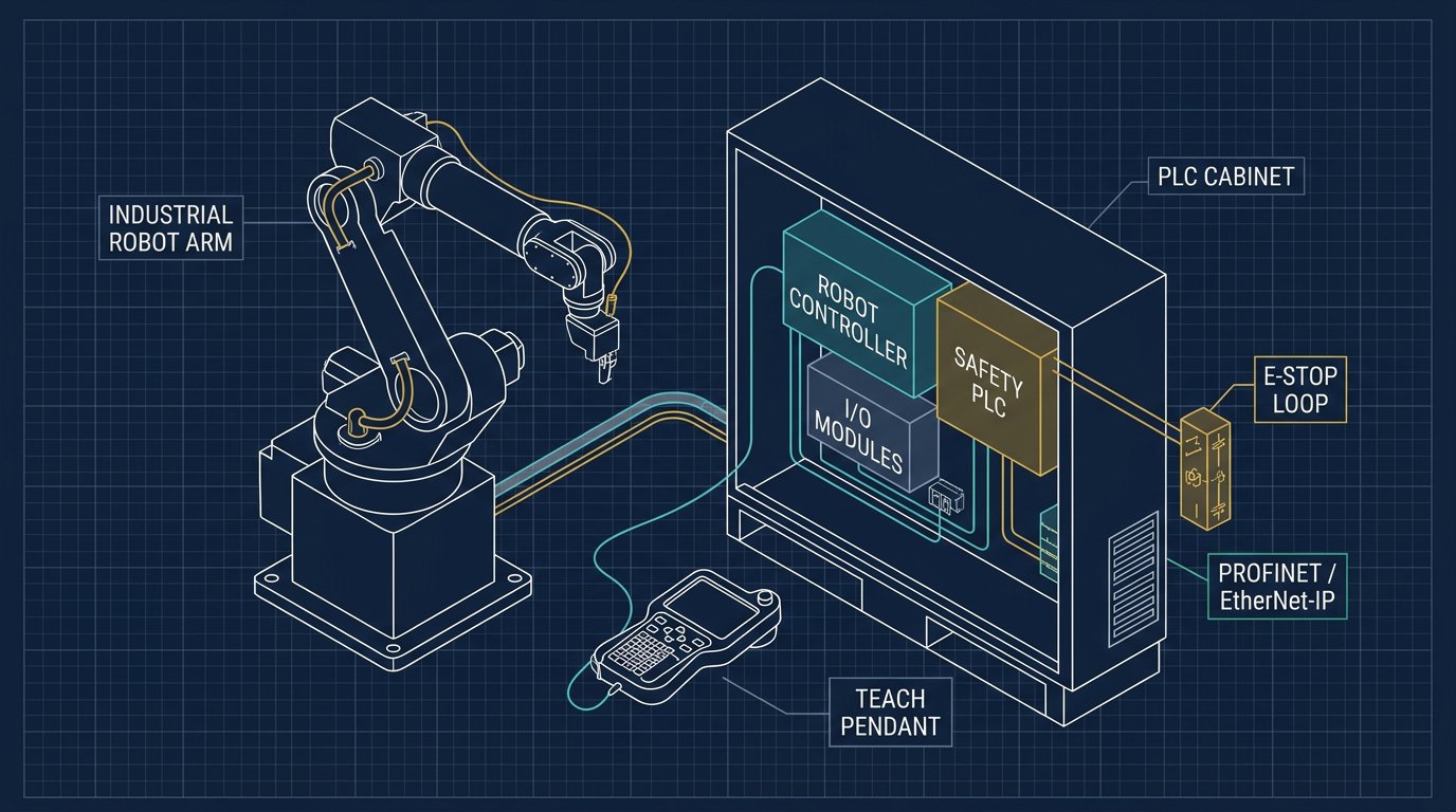
Dividing responsibility: PLC vs. robot controller
A robot controller such as a FANUC R-30iB (or its later R-30iB Plus / R-30iB Mate variants) is a closed, real-time motion system: it reads its own encoders, closes its own servo loops, and executes its own teach-pendant program. A PLC such as a Siemens S7-1500, running in TIA Portal, is a general-purpose sequencer: it scans I/O, runs the cell's logic, and talks to other stations. Neither system should try to do the other's job. Trying to stream individual joint targets from a PLC to a robot controller is unusual, fragile, and rarely how commercial cells are built — the exchange is almost always a handful of handshake bits and a small number of integers (program number, part ID, fault code).
This separation also matters for maintainability: a robot programmer can change the internal motion program without touching PLC logic, as long as the handshake contract at the boundary stays the same, and vice versa.
Choosing a communication link: PROFINET, EtherNet/IP, or discrete I/O
Most modern robot controllers offer an optional fieldbus card so the controller appears to the PLC as an I/O device on the network. Siemens PLCs commonly use PROFINET; Allen-Bradley/Rockwell PLCs commonly use EtherNet/IP. The robot vendor's option catalog determines which protocols are actually available for a given controller and firmware version — always confirm the exact option code with the robot vendor before assuming a protocol is supported.
| Option | Typical fit | Trade-off |
|---|---|---|
| Discrete digital I/O | Small cells, few signals, simple handshake | Easy to troubleshoot with a multimeter; wiring grows with signal count; no built-in diagnostics. |
| PROFINET | Siemens-centric plants, many signals, diagnostics needed | Reduces wiring to one network cable; adds network configuration and a dependency on network health. |
| EtherNet/IP | Rockwell/Allen-Bradley-centric plants | Same trade-offs as PROFINET, different ecosystem and tag mapping conventions. |
Whichever link is chosen, treat it as a data source that can be stale or absent — never assume the network guarantees delivery at a fixed rate. That assumption belongs in the handshake design, covered next.
Designing the handshake signal set
Regardless of the physical link, most PLC-robot interfaces converge on a similar signal set. Naming varies by integrator, but the functions below appear in nearly every cell:
| Signal | Direction | Purpose |
|---|---|---|
| Program / Job Select | PLC → Robot | Tells the controller which taught program or part variant to run next. |
| Cycle Start | PLC → Robot | Requests the robot to begin the selected program once it is ready. |
| Robot Ready | Robot → PLC | Confirms the controller is in automatic mode, faults are clear, and it can accept a start. |
| Robot Busy / In-Cycle | Robot → PLC | Lets the PLC know the robot is mid-motion and should not be re-triggered. |
| Cycle Done | Robot → PLC | Pulses or latches once the requested program has finished successfully. |
| Fault / Alarm Code | Robot → PLC | Reports that the controller has stopped on an error, often with a numeric code for the HMI. |
| Fault Reset | PLC → Robot | Requests the controller to clear a recoverable fault after the cause has been addressed. |
| Heartbeat / Sequence Counter | Both directions | Detects a frozen or disconnected link so stale data is never mistaken for a live signal. |
A frequent design mistake is treating "Cycle Done" as reliable proof that the robot is safe to approach or that the part is good. It only proves the program ran to completion — separate sensors (part-present, vision confirmation, torque feedback) should confirm the actual outcome.
Structured Text example: a handshake state machine
The following is a simplified Structured Text (ST) sketch, one of the languages defined by IEC 61131-3 alongside Ladder Diagram, Function Block Diagram, and Sequential Function Chart. It illustrates the shape of a handshake state machine, not a vendor-specific, production-ready block — adapt tag names, timers, and fault handling to the actual PLC platform and robot I/O map.
TYPE CellState : (IDLE, WAIT_ROBOT_READY, REQUEST_START, WAIT_DONE, FAULT);
END_TYPE

VAR
    state          : CellState := IDLE;
    robotReady     : BOOL;      // Robot -> PLC
    robotBusy      : BOOL;      // Robot -> PLC
    robotDone      : BOOL;      // Robot -> PLC
    robotFault     : BOOL;      // Robot -> PLC
    cycleStart     : BOOL;      // PLC -> Robot
    faultReset     : BOOL;      // PLC -> Robot
    heartbeatIn    : BOOL;      // toggled by robot side
    heartbeatOut   : BOOL;      // toggled by PLC side
    hbTimer        : TON;       // link-loss watchdog
    hbTimeout      : BOOL;
END_VAR

// Toggle our own heartbeat every scan the program is healthy
heartbeatOut := NOT heartbeatOut;

// Watchdog: if the robot's heartbeat hasn't changed, start the timer
hbTimer(IN := NOT heartbeatIn, PT := T#2S);
hbTimeout := hbTimer.Q;

CASE state OF
    IDLE:
        cycleStart := FALSE;
        IF robotReady AND NOT hbTimeout THEN
            state := REQUEST_START;
        END_IF;

    REQUEST_START:
        cycleStart := TRUE;
        IF robotBusy THEN
            cycleStart := FALSE;
            state := WAIT_DONE;
        END_IF;

    WAIT_DONE:
        IF robotDone THEN
            state := IDLE;
        ELSIF robotFault OR hbTimeout THEN
            state := FAULT;
        END_IF;

    FAULT:
        cycleStart := FALSE;
        // Operator or higher-level logic must clear the root cause first
        IF faultReset AND NOT robotFault AND NOT hbTimeout THEN
            state := IDLE;
        END_IF;
END_CASE;
Three details matter more than the syntax itself: the watchdog transitions to FAULT on its own, the PLC never asserts cycleStart without first checking robotReady, and clearing a fault requires both an explicit operator action (faultReset) and confirmation that the underlying condition is actually gone.
Safety architecture: what stays outside the standard PLC
The handshake logic above runs in the standard, non-safety part of the PLC program. It must never be the only thing standing between a person and a moving robot. Emergency stop, guard-door interlocks, and any speed- or force-limiting function belong in a safety-rated controller, safety relay, or safety I/O module, architected to the category and performance level the cell's risk assessment calls for (per ISO 13849-1 concepts such as Category 3 and Performance Level d, or the equivalent SIL framework under IEC 62061). Which category and PL apply is a risk-assessment output, not a fixed number that transfers automatically from one cell to another.
In practice, most cells use hardwired safety relays or a safety PLC for the e-stop chain and guard monitoring, with the standard PLC and robot controller handling only the production handshake. The two systems typically share status information (e.g., "safety circuit OK") so the standard logic can react gracefully, but the safety function itself does not depend on the standard PLC program executing correctly.
Common integration failures
| Symptom | Likely cause | Check and correction |
|---|---|---|
| Robot starts a stale or wrong program | Program-select signals changed after Cycle Start was already latched | Only sample program-select values while the robot is in IDLE/Ready, before asserting Cycle Start. |
| Cell hangs with no fault indication | Fieldbus link frozen; last-known values still look valid to the PLC | Add a heartbeat/sequence counter on both sides and a timeout that forces a defined fault state. |
| Robot double-triggers on noisy signal | Cycle Start read as a level instead of a rising edge, or contact bounce on discrete I/O | Trigger on a rising edge internally and add debounce/filtering on physical inputs. |
| Operator resets fault but robot immediately re-faults | Fault Reset cleared before the physical cause (jam, part out of position) was actually resolved | Require the fault condition itself to read clear before accepting a reset, not just an operator button press. |
| PLC and robot disagree about cell state after a network restart | No re-synchronization logic after a fieldbus reconnect | Force both sides back to a known IDLE state and re-establish the heartbeat before allowing any Cycle Start. |
Commissioning checklist
- Confirm which fieldbus options are actually licensed and installed on the specific robot controller and firmware version — not just what the vendor catalog lists in general.
- Map every handshake signal by name on both sides (PLC tag and robot I/O point) before writing logic, and keep that map as a living commissioning document.
- Test loss of network/fieldbus communication deliberately; confirm the cell reaches a defined, safe state rather than freezing on stale data.
- Verify the safety chain (e-stop, guard doors) functions with the standard PLC program stopped or faulted — safety must not depend on standard logic running.
- Confirm the robot's "Ready" and "Fault" outputs actually reflect controller state under test conditions (forced fault, mode switch, program stop) rather than assuming the documentation is accurate for this specific configuration.
- Record firmware versions, fieldbus option part numbers, and I/O maps for both the PLC and the robot controller as part of the handover documentation.
Sources
For current specifications, confirm directly with the manufacturer documentation rather than relying on a summary: the Siemens S7-1500 product page, the FANUC R-30iB controller page, the IEC 61131-3 standard for programming languages, the ISO 13849-1 information page for safety-related control system categories, and PROFINET / PI International for fieldbus specifications. Standards editions and product options change; verify the current revision before specifying a cell.
Related robot-arm guides
Continue with the ROS 2 robot control guide, the robot arm safety standards overview, and the gripper design guide. Together with this article, they cover the control, communication, and mechanical decisions in a typical industrial robot cell.
Frequently asked questions
Does the PLC or the robot controller run the motion program?
The robot controller runs the motion program and interpolates the joints. The PLC does not send trajectories; it exchanges a small set of discrete or integer signals with the robot controller and coordinates the rest of the cell.
Is PROFINET required to integrate a PLC with a robot?
No. PROFINET, EtherNet/IP, and plain digital I/O are all valid options. The right choice depends on signal count, diagnostics needs, and what the robot's fieldbus option card supports.
Can the safety function run entirely inside the standard PLC program?
Not for safety-rated stopping and guarding functions. Those must run in a safety-rated controller, safety relay, or safety I/O, achieving the performance level or category the risk assessment requires.
What does "Category 3, PL d" mean in a robot cell?
It is a safety architecture classification from ISO 13849-1. Category 3 requires that a single fault not cause loss of the safety function; PL d is a target reliability band. Whether it's sufficient depends on the cell's own risk assessment.
Why does the handshake need a heartbeat or watchdog?
Fieldbus links can freeze or disconnect without an obvious fault. A heartbeat lets each side detect that the other has stopped updating, so the cell goes to a safe state instead of acting on stale data.