Standards Overview: Who Requires What, and Why It's Confusing
Robot safety compliance in North America is not governed by a single law that says "your robot must meet standard X." Instead, it works through a layered system: government regulators (OSHA in the USA, provincial ministries of labour in Canada) set broad duty-of-care requirements, and consensus standards developed by industry bodies — ANSI/RIA in the United States, CSA in Canada, and ISO internationally — define the specific technical criteria that are recognized as evidence of due diligence.
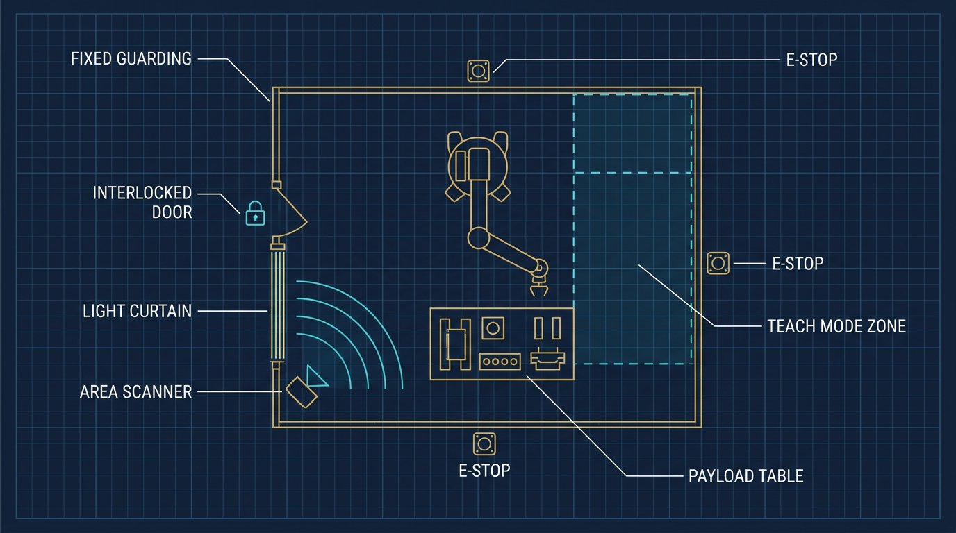
In practice, this means a plant in Michigan and a plant in Ontario building the exact same robot cell will reference two different standard numbers — ANSI/RIA R15.06 and CSA Z434 respectively — even though both standards are harmonized with the same underlying ISO 10218 framework and require nearly identical engineering controls. Understanding this relationship is the first step to building a compliance program that doesn't duplicate effort across borders.
ANSI/RIA R15.06: The United States Standard
ANSI/RIA R15.06, developed by the Robotic Industries Association (now part of the Association for Advancing Automation, A3) and accredited by the American National Standards Institute, is the primary consensus standard for industrial robots and robot systems in the United States. It defines requirements covering:
- Design and construction requirements for the robot manufacturer, including stopping functions and hazardous energy control.
- Integration requirements for the entity that builds the complete robot system, including safeguarding, risk assessment, and the interface between the robot and other equipment.
- Requirements for the user/employer, including training, maintenance procedures, and periodic re-verification when the application changes.
OSHA does not enforce ANSI/RIA R15.06 directly as a regulation, but it can be cited as evidence of the recognized industry standard of care under the General Duty Clause, and OSHA's own robotics guidance documents reference it. In practice, most insurers, auditors, and corporate EHS departments in the USA treat conformance with the current edition of R15.06 as the baseline expectation for any new robot installation.
CSA Z434: The Canadian Standard
CSA Z434, published by the CSA Group, is the equivalent standard for Canada and is structured very similarly to ANSI/RIA R15.06 — both are harmonized against the ISO 10218 series, so the core technical requirements (safeguarding distances, stop categories, risk assessment methodology) are substantially aligned. The practical differences show up mostly in referenced provincial regulations, since occupational health and safety in Canada is primarily a provincial jurisdiction rather than a single federal framework.
A manufacturer installing the same robot cell design in both Michigan and Ontario should expect the engineering work — safeguarding devices, safety distances, risk assessment documentation — to transfer almost directly between the two standards, with the main adjustments being provincial OHS paperwork, electrical code references (CSA vs. NEC), and any province-specific machine guarding regulations.
ISO 10218-1/-2: The International Baseline Both Standards Build On
ISO 10218-1 covers the robot itself (manufacturer requirements) and ISO 10218-2 covers the integrated robot system (integrator and end-user requirements). Both ANSI/RIA R15.06 and CSA Z434 are built to align closely with this international framework, which is why compliance documentation prepared for a North American plant is often directly reusable for a sister facility overseas, with only local regulatory references changed.
The 2011 edition of ISO 10218 introduced explicit provisions for collaborative operation, which laid the groundwork for the modern generation of collaborative robots (cobots) now common in packaging, machine tending, and small-parts assembly.
Collaborative Robots and ISO/TS 15066
ISO/TS 15066 is a technical specification that supplements ISO 10218 specifically for collaborative robot applications. It defines four recognized collaborative operating modes and provides guidance on the pain and injury thresholds used to set force and pressure limits for applications where a robot and a person may share the same workspace without a physical barrier.
| Collaborative Mode | How It Works | Typical Use Case |
|---|---|---|
| Safety-rated monitored stop | Robot fully stops when a person enters the collaborative workspace | Manual load/unload stations |
| Hand guiding | Operator physically guides the robot using a hand-operated device | Teaching and programming by demonstration |
| Speed and separation monitoring | Robot slows or stops based on real-time distance to a person | Shared workspace with safety-rated scanners |
| Power and force limiting | Robot's inherent design limits contact force/pressure below injury thresholds | True cobots (e.g., UR, Techman) operating without fencing |
A critical point that gets misunderstood constantly on the plant floor: buying a robot marketed as a "cobot" does not automatically satisfy ISO/TS 15066 for every application. The end-effector, workpiece geometry, payload, and speed of the specific task must still be assessed. A power-and-force-limited robot arm carrying a payload with sharp edges or pinch points can still require fencing or a reduced speed profile after the risk assessment is complete.
"The word 'collaborative' describes a category of robot, not a guarantee of safety. Every application still needs its own risk assessment — the robot's inherent design is only one variable in the equation."— Robotics Engineering, Industrial Safety Desk
How a Robot Risk Assessment Actually Works
Every major standard referenced in this guide — ANSI/RIA R15.06, CSA Z434, and ISO 10218 — requires a documented risk assessment before a robot system is put into service, and again whenever the application changes significantly. The underlying methodology follows the general machinery risk assessment framework in ISO 12100.
- Define the limits of the system. Document the robot model, payload, reach, end-effector, workpiece, task, and the physical boundaries of the cell across every phase of operation — production, teaching, and maintenance.
- Identify hazards. List every hazard: impact, crushing, shearing, pinch points, entanglement, ejected parts, electrical hazards, and hazards introduced specifically by the end-of-arm tooling.
- Estimate and evaluate risk. For each hazard, estimate the severity of potential injury, frequency of exposure, and possibility of avoidance, then determine whether the residual risk is acceptable.
- Apply risk reduction in order of priority. Eliminate the hazard through design first, then engineering safeguards (fencing, light curtains, scanners), then administrative controls and training, then PPE as the last layer.
- Verify and document. Test the implemented safeguards, measure safety distances and stopping performance, and keep written documentation on file for audits and future modifications.
This process should be repeated any time the cell is modified — a new end-effector, a change in cycle speed, or relocation of the cell within the plant are all common triggers that require re-verification under both ANSI/RIA R15.06 and CSA Z434.
Safeguarding Devices: Which One Fits Which Application
Once the risk assessment identifies where engineering controls are needed, the choice of physical safeguarding device depends heavily on the geometry of the cell and how frequently people need access.
| Device | Best For | Limitation |
|---|---|---|
| Fixed physical guarding | Zones with no routine human access | Requires tools to remove; not practical for frequent access points |
| Interlocked access gates | Doors used for loading, unloading, or occasional maintenance | Must be paired with a safety relay/PLC that removes power on opening |
| Light curtains | Straight-line access openings such as conveyor infeed/outfeed | Only protects the plane of the curtain, not the full 3D space |
| Safety laser scanners | Irregular floor areas, multiple approach directions, speed reduction zones | Higher cost; requires careful configuration of protective fields |
| Safety mats | Floor-level presence detection near a hazard zone | Detects presence but not distance or direction of approach |
| Power and force limiting (inherent design) | True collaborative tasks with light payloads and no pinch hazards | Does not eliminate hazards from the tool or workpiece itself |
A frequent design pattern in North American plants combines a light curtain at the primary operator access point with fixed guarding around the remaining perimeter, and a safety-rated scanner in zones where forklifts or AGVs also need clearance — no single device is expected to cover every hazard in a complex cell.
Safety Categories and Performance Levels: What PLd and PLe Actually Mean
When a safety device is specified, it's rated according to ISO 13849-1 using a Performance Level (PL a through PL e) or, under the older but still-referenced IEC 62061 framework, a Safety Integrity Level (SIL). These ratings describe how reliably the safety function performs under fault conditions — not how "advanced" the equipment is.
| Performance Level | Typical Application | Common Architecture |
|---|---|---|
| PL c | Lower-risk auxiliary functions | Single-channel with monitoring |
| PL d | Standard industrial robot E-stop and interlocked guards | Dual-channel with fault detection |
| PL e | High-risk applications, heavy payloads, high-speed robots | Dual-channel, cross-monitored, redundant safety PLC or relay |
Most standard industrial robot cells with fencing and interlocked gates are designed to PL d. Cells with higher-consequence hazards — very high payload, high approach speeds, or reduced separation distances — are more commonly specified at PL e, using a dual-channel safety relay or a certified safety PLC such as those referenced in our robot arm PLC integration guide.
Common Compliance Mistakes Seen on the Plant Floor
- Treating a "cobot" label as a complete safety solution without assessing the specific tool, payload, and workpiece hazards of the actual application.
- Never re-running the risk assessment after a change. A new end-effector, faster cycle time, or relocated cell all require re-verification, but this step is frequently skipped after the initial installation.
- Bypassing safety circuits "temporarily" during troubleshooting and never restoring them — one of the most cited root causes in robot-related incident investigations.
- Confusing "meets CE marking" with "compliant with ANSI/RIA R15.06 or CSA Z434." CE marking reflects European Machinery Directive compliance and does not automatically satisfy North American consensus standards, though the underlying engineering is often similar.
- Underestimating stopping distance calculations when positioning light curtains or scanners, leading to a minimum safety distance that doesn't account for the robot's actual stopping performance plus human approach speed.
Related Resources
- Integrating 6-Axis Robot Arms with Siemens and Allen-Bradley PLCs
- Robot Arm ROI Calculator: Payback Period & TCO Guide
- 6-Axis Robot Arm Maintenance Schedule: Preventive Care for Maximum Uptime
- The Complete 6-DOF Robot Arm Guide (2026)
Sources and References
- Association for Advancing Automation (A3) — ANSI/RIA R15.06 standard development and robotics safety resources.
- CSA Group — CSA Z434 industrial robot and robot system safety requirements.
- International Organization for Standardization (ISO) — ISO 10218-1, ISO 10218-2, ISO/TS 15066, and ISO 12100 series.
- Occupational Safety and Health Administration (OSHA) — Robotics industry guidance and General Duty Clause references.
- International Federation of Robotics (IFR) — Global robot safety and adoption context.
Frequently Asked Questions
What safety standard applies to industrial robot arms in the United States?
In the United States, ANSI/RIA R15.06 is the main consensus safety standard for industrial robots and robot systems. OSHA may use recognized consensus standards, together with applicable OSHA requirements such as lockout/tagout rules, when assessing workplace safety.
What standard applies to robot systems in Canada?
CSA Z434 is the principal Canadian standard for industrial robots and robot systems. Provincial occupational health and safety requirements may also apply depending on where the robot cell is installed.
Are collaborative robots safe without fences?
Not automatically. A collaborative robot is not inherently safe in every installation. The complete application, including the tool, payload, sharp edges, workpiece, speed, reach, pinch points, and surrounding equipment, must be assessed through a documented risk assessment.
What is the difference between a light curtain and a safety laser scanner?
A light curtain creates a straight optical detection field and is commonly used at access openings. A safety laser scanner creates configurable two-dimensional protected zones and is useful where fixed guarding is impractical or where a robot must slow down as a person approaches.
Who is responsible for robot cell safety compliance?
Responsibility is shared across the robot manufacturer, system integrator, employer, safety professional, and facility management. The employer operating the cell must ensure that the final installed system is risk assessed, safeguarded, documented, maintained, and used by trained personnel.