The Engineering Role of End-of-Arm Tooling (EOAT)
A 6-axis robot arm is a generic positioning device; the End-of-Arm Tooling (EOAT)—commonly called a gripper—is what actually interfaces with the part. Selecting the wrong gripper geometry or force profile can damage parts, crash the robot, or cause payloads to be dropped mid-cycle. EOAT design is therefore the most critical mechanical integration step in any robotic cell.
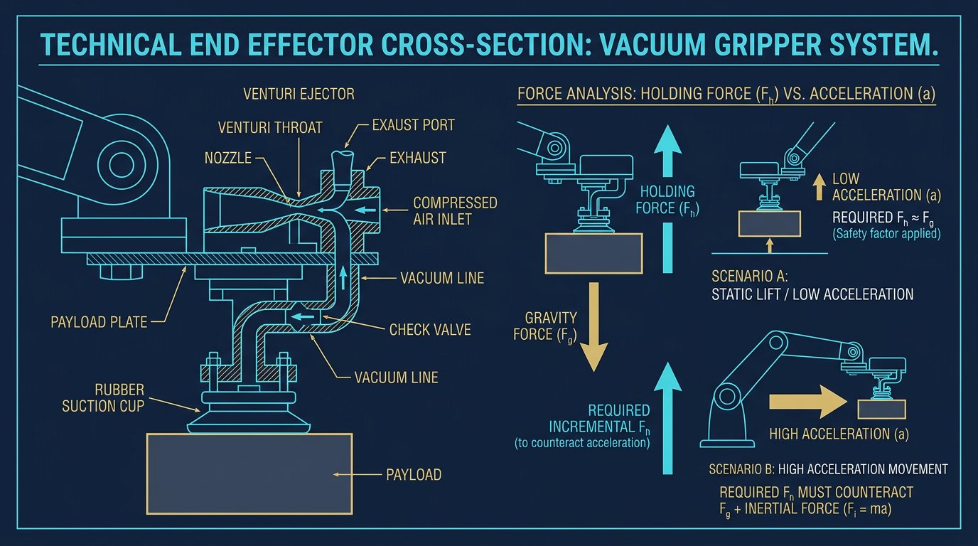
The design process begins with analyzing the part: its mass, surface friction, material permeability, and geometry. From there, engineers select a gripping technology—vacuum, magnetic, or mechanical—and size it to handle both the static weight and the dynamic acceleration forces generated by the robot's motion.
A robot is only as good as its gripper. A $50,000 arm fails instantly if a poorly sized suction cup drops the part during a high-speed transfer.- Robotics Engineering, EOAT Design Division
Vacuum Grippers: Porous and Non-Porous Handling
Vacuum technology is the most widely used EOAT for packaging, sheet metal handling, and glass installation. It uses suction cups (usually silicone, polyurethane, or nitrile) sealed against a surface. A vacuum pump or venturi ejector drops the pressure inside the cup, allowing atmospheric pressure to push the part against the cup.
The theoretical holding force is calculated as F = ΔP × A (Pressure differential × Effective cup area). A standard industrial vacuum system operates around -0.7 bar. A cup with a 15 cm² effective area yields roughly 105 N of holding force at sea level. However, engineers must apply a safety factor of 2.0x to 4.0x depending on the acceleration of the robot and the surface porosity. For cardboard or MDF (porous materials), a portion of the vacuum bleeds through the material, drastically reducing ΔP and requiring larger cups or higher flow ejectors.
Cup Geometry Selection
- Flat Suction Cups: Best for smooth, rigid surfaces (glass, polished steel). Low volume, fast response.
- Bellows Cups: Best for uneven or curved surfaces. The accordion shape compensates for height differences but requires more vacuum volume, slowing cycle times.
- Oval Cups: Used for long, narrow parts (like extrusions or tubes) where round cups won't fit.
Magnetic Grippers: Ferrous Material Handling
When handling ferrous metals (steel, iron), magnetic grippers offer high force density without needing a perfectly flat sealing surface. There are two primary architectures:
Electromagnetic Grippers
These use a coil wound around a ferrous core. When 24 V DC is applied, a magnetic field is generated. They offer very fast response times (often 0.15 s to full hold) and variable holding force. The critical engineering caveat is failsafe behavior: if power is lost, the magnetic field collapses instantly. For vertical lifts, a UPS or mechanical backup is mandatory.
Switchable Permanent Magnetic Grippers
These use rare-earth Neodymium magnets and rely on a pneumatic actuator to physically shift the internal magnetic array. When "off," the flux is routed internally; when "on," the flux is directed into the part. Because they do not require electrical power to maintain hold, they are failsafe against power loss. The trade-off is a longer release time (approx. 0.3 s) and the requirement for a pneumatic supply to the wrist.
A critical sizing factor for magnets is the "air gap." Paint, rust, mill scale, or warped sheet metal creates a non-magnetic barrier that drastically reduces holding force. A 1 mm air gap can reduce a 150 N magnet's effective force by over 50%.
Mechanical Grippers: Jaws and Claws
Mechanical grippers use actuated fingers or jaws to physically clamp a part. They are essential for non-ferrous, non-flat parts (e.g., plastic housings, machined aluminum blocks). Suppliers like Schunk and Zimmer dominate this space.
| EOAT Type | Mechanism | Best Application Fit | Key Limitation |
|---|---|---|---|
| Vacuum Cup (Piab) | Negative air pressure | Sheet metal, glass, cardboard packaging | Requires smooth, non-porous surface for max force |
| Magnetic | Electromagnet or switchable permanent | Steel blanks, automotive stamping, CNC bar stock | Ferrous materials only; residual magnetism on part |
| Parallel Mechanical | Pneumatic or electric rack-and-pinion jaws | Machined parts, irregular geometry, assembly tasks | Requires custom fingers; adds weight to wrist |
| Soft Robotics / Compliant | Fragile parts, food handling, varying geometries | Low payload capacity; slower cycle times |
Parallel vs. Angular Jaws
Parallel jaws maintain a constant 90-degree relationship to the gripper body as they open and close, ensuring the part is centered every time. Angular jaws pivot on a hinge; they are cheaper and faster but the part center shifts depending on its size, which complicates robot programming.
For high-precision assembly, electric servo grippers are preferred over pneumatic. Servo grippers allow precise control of jaw position (e.g., a 60 mm opening to handle one part, a 45 mm opening for another) and force feedback, preventing delicate parts from being crushed.
Integration: TCP, Weight, and Moment of Inertia
Once a gripper is selected, it must be mechanically mounted and electronically integrated. All industrial robot wrists terminate in a standard bolt circle, defined by ISO 9409-1 (e.g., a 50 mm or 63 mm circle). An adapter plate is machined to mate the gripper to this flange.
Defining the Tool Center Point (TCP)
The robot controller needs to know exactly where the "tip" of the gripper is. This is the Tool Center Point. For a vacuum cup, the TCP is usually the center of the cup's face. For a mechanical claw, it is the geometric center between the jaws at the gripping plane. The TCP must be taught to the robot using a 4-point calibration method (touching a fixed reference point from four different orientations).
Payload and Inertia Derating
A robot's rated payload (e.g., 20 kg) is the maximum mass it can carry at the flange. The EOAT itself has mass. If the gripper weighs 5 kg, the maximum part weight is reduced to 15 kg. Furthermore, the gripper extends the leverage on the wrist joints. The moment of inertia of the combined gripper and part must be checked against the robot's wrist torque limits. Failing to do this will cause the robot to fault on acceleration or prematurely wear out the J4, J5, and J6 gears.
Implementation Checklist for EOAT Design
- Calculate Dynamic Forces: Size the gripper for the robot's maximum acceleration, not just static gravity loads. A 2 kg part undergoing 2g of acceleration requires a gripper capable of holding 4 kg+ safely.
- Minimize EOAT Mass: Use aluminum or carbon fiber for adapter plates and fingers. Every 100 grams saved on the wrist translates to faster cycle times and longer robot life.
- Route Utilities Safely: Route pneumatic lines and sensor cables through the center of the wrist flange if possible, to prevent snags during J6 (wrist roll) rotations.
- Add Part Presence Sensors: Never assume a part was picked. Install proximity sensors or vacuum switches on the EOAT to confirm part presence before the robot moves.
- Design Failsafes: If the cell E-stops during a vertical lift, what happens to the part? Ensure pneumatic grippers have check valves to maintain grip pressure, or use permanent magnets that don't require power.
- Comply with ISO 12100: Ensure the EOAT design does not introduce pinch points or sharp edges that could injure an operator teaching or maintaining the cell, per machinery safety standards.
Related Resources
- Magnetic Gripper Design for 6-Axis Robot Arms: Ferrous Material Handling
- Force and Torque Sensors for 6-DOF Robot Arms: Integration & Calibration
- Robot Arm Calibration Techniques: Accuracy, Repeatability & Error Correction
- Carbon Fiber Components for Lightweight 6-DOF Robot Arms
- The Complete 6-DOF Robot Arm Guide (2026)
Sources and Methodology
Technical parameters in this guide (e.g., vacuum pressure of -0.7 bar, magnetic air gap derating, 2-4x safety factors) represent standard industrial practices for EOAT design. Robotics Engineering references ISO 9409-1 for mechanical interfaces and ISO 12100 for machinery safety. Supplier specifications (Schunk, Piab, Robotiq, Zimmer) were used to validate force curves and response times. Always calculate the specific moment of inertia for your EOAT geometry against your robot's wrist torque limits before finalizing a design.
How do you calculate the holding force of a vacuum gripper?
The theoretical holding force is calculated by multiplying the vacuum pressure by the effective area of the suction cup (F = P x A). In practice, engineers must apply a safety factor (typically 2x to 4x) to account for acceleration forces, surface porosity, and air leaks.
What happens to a magnetic gripper if power is lost?
If an electromagnetic gripper loses power, the magnetic field collapses and the part will drop. To prevent this in vertical lifting applications, engineers use permanent magnetic grippers with pneumatic release mechanisms, which hold the part without power and require air pressure only to let go.
How does gripper weight affect robot payload capacity?
The weight of the End-of-Arm Tooling (EOAT) must be subtracted from the robot's maximum payload rating. For example, a robot with a 10 kg payload carrying a 3 kg gripper can only handle a 7 kg part. Additionally, heavy Grippers increase the moment of inertia on the wrist joints, which may require slower cycle times.