Why Choose Magnetic Grippers for Ferrous Automation?
When a 6-axis robot arm needs to move steel plates, stamped blanks, or welded tubes, vacuum cups and mechanical jaws often fall short. Vacuum systems struggle with porous or oily surfaces, and mechanical grippers can deform thin sheet metal or require complex changeovers for different part geometries. Magnetic grippers solve these issues by securing the ferrous part across its entire surface area without mechanical clamping.
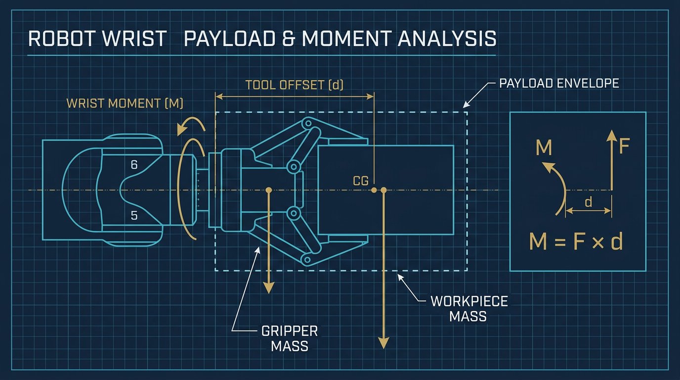
However, designing a magnetic end-effector requires more than bolting a magnet to a tool changer. Engineers must balance holding force against the robot's payload limits, manage power fail-safes, and account for the physical properties of the material being lifted.
The end-effector defines what a robot can do. Selecting the wrong gripper turns a $50,000 robot into an expensive paperweight.- Robotics Engineering, Manufacturing Intelligence Report 2026
Electromagnets vs. Permanent Magnets: Design Trade-offs
The first engineering decision in magnetic gripper design is selecting the active technology. Each has distinct implications for control architecture, safety, and cycle time.
Electromagnetic Grippers
Electromagnets use an electric coil wound around a ferrous core to generate a magnetic field when energized—typically at 24 V DC. They offer exceptionally fast response times (often around 0.15 seconds to full hold) and allow variable holding force by adjusting the current. The primary drawback is failsafe behavior: if power is lost, the magnetic field collapses and the part drops. This necessitates uninterruptible power supplies (UPS) or mechanical safety catches in vertical lift applications.
Switchable Permanent Magnetic Grippers
These grippers use rare-earth permanent magnets (like Neodymium) as their holding source. Instead of turning the magnet "off" electrically, a small pneumatic or electric actuator physically shifts the internal magnetic array, redirecting the flux into the part or internally back into the gripper body. Because the holding force is generated by permanent magnets, a power failure does not result in a dropped part. The trade-off is a slightly longer release time and the requirement for a pneumatic supply line on the wrist.
| Gripper Type | Typical Holding Force | Response/Release Time | Best Application Fit |
|---|---|---|---|
| Vacuum Cup (Piab) | ~50 N / cup | 0.2 s | Smooth, non-ferrous surfaces (glass, plastic) |
| Electromagnetic (Schmalz) | 150 N+ | 0.15 s | High-speed stamping, sorted ferrous parts |
| Switchable Permanent | 150 N+ | 0.3 s | Heavy steel plates, vertical lifts, power-loss critical |
| Parallel Mechanical (Schunk) | 200 N grip | 0.3 s | Irregular shapes, non-ferrous assembly |
Calculating Usable Holding Force: The Air Gap Problem
Manufacturer datasheets state holding force under ideal conditions: a thick, flat, clean steel plate in direct contact with the pole face. In real-world automation, these conditions rarely exist.
Any non-magnetic barrier between the gripper and the part creates an "air gap"—including paint, mill scale, rust, oil films, or warped sheet metal. Magnetic force drops off exponentially with distance. A 1-millimeter air gap can reduce the effective holding force of a 150 N magnet by 40% to 60%.
When sizing a magnetic gripper, engineers must calculate the required force based on the worst-case scenario:
- Part Weight (Mass × Gravity): The baseline gravitational load.
- Acceleration/Deceleration Forces: When the 6-axis arm moves dynamically, the gripper must resist shear forces holding the part laterally.
- Safety Factor: Typically a 3:1 safety factor is applied for vertical lifts and high-dynamic motion.
- Material Thickness: Thin sheet metal saturates magnetically and cannot absorb the full magnetic flux, further reducing holding force.
Integration on the 6-Axis Wrist
Integrating a magnetic gripper requires mechanical, electrical, and software coordination. The gripper mounts to the robot wrist via a standard interface, commonly an ISO 9409-1 flange.
Electrically, the robot controller must supply 24 V DC to the gripper solenoids and monitor discrete inputs (part present sensors). Because magnets inherently retain residual magnetism on the part after release, a demagnetization cycle (rapidly reversing the polarity at decreasing amplitude) is often programmed into the robot's release routine to ensure the blank drops cleanly. Wiring and pneumatic hoses must be routed through the robot's dress pack to prevent snags during wrist roll motions.
Safety and Compliance (USA & Canada)
Magnetic grippers fall under standard industrial robot safety frameworks. In North America, cell design must comply with ANSI/RIA R15.06 (USA) and CSA Z434 (Canada). Electrical wiring on the end-effector must adhere to IEC 60204-1.
A critical risk assessment question for magnetic grippers is "What happens if the robot E-stops mid-cycle?" If using electromagnets, the E-stop circuit must trigger a localized UPS hold or mechanical brake to prevent parts from falling onto operators or machinery.
Implementation Checklist for Buyers
- Verify Material Compatibility: Confirm the ferrous content and magnetic permeability of the target parts (austenitic stainless steels, for example, are largely non-magnetic).
- Profile the Air Gap: Measure the worst-case surface condition (paint, oil, warp) and derate the magnet's nominal holding force accordingly.
- Calculate Dynamic Loads: Ensure the gripper can handle shear forces during maximum robot acceleration, not just static vertical lifts.
- Define Failsafe States: Decide behavior for power loss. Use switchable permanent magnets for heavy lifts or add mechanical backups for electromagnets.
- Plan Demagnetization: If parts stick after release, program an electrical demag pulse or add a mechanical stripper plate to the fixture.
- Manage Cable Dress: Route 24V DC and sensor cables to avoid fatigue at the wrist axis during continuous 360-degree rolls.
Related Resources
- Harmonic Drive Review for 6-DOF Robot Arms: Precision & Backlash
- Dust Protection for 6-DOF Robot Arms: Seals, Covers & IP Ratings
- Area Scanner Setup for Robot Arms: 3D Safety Monitoring & Interlocks
- The Complete 6-DOF Robot Arm Guide (2026)
Sources and Methodology
Technical parameters in this guide (e.g., 150 N holding force, 0.15 s release time, 24 V DC operation) represent typical specifications for mid-range industrial magnetic EOATs. Robotics Engineering references primary manufacturer datasheets (Schmalz, Goudsmit) and international safety standards (ISO, IEC, ANSI/RIA). Always verify final holding-force calculations with the specific gripper manufacturer for your application's material thickness and air-gap conditions.
What is the difference between an electromagnetic and a permanent magnetic gripper?
Electromagnetic grippers require a continuous 24V DC power supply to maintain holding force, offering fast response times but risking part drop during power loss. Permanent magnetic grippers hold parts without power and use a brief pneumatic or mechanical pulse to break the magnetic field for release, making them safer for power failures.
How does air gap affect magnetic gripper holding force?
Even a small air gap caused by paint, rust, dust, or warped sheet metal drastically reduces the holding force of a magnetic gripper. Engineers must size the gripper based on the worst-case surface condition, not just the theoretical flat-sheet specification.
What standards apply to magnetic grippers on industrial robots in North America?
Mechanical mounting interfaces typically follow ISO 9409-1. Electrical safety and wiring must comply with IEC 60204-1, while overall robot cell safety in the USA and Canada falls under ANSI/RIA R15.06 and CSA Z434 respectively.