Why Use Area Scanners for Robot Safety?
Traditional physical guards and light curtains are effective for caged robotics, but they limit flexibility. When a manufacturing process requires an operator to interact with a 6-axis robot arm—whether for loading heavy stock, inspecting welds, or clearing minor jams—hard guarding becomes an obstacle. Area scanners (also known as safety laser scanners) solve this by creating invisible, programmable protective fields.
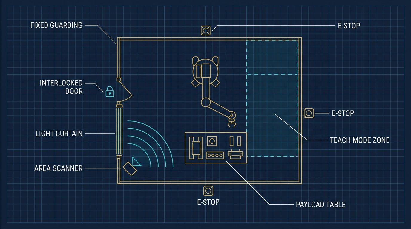
Unlike light curtains, which only detect a beam break at a specific height, modern 3D area scanners monitor a volumetric space. They allow a robot to slow down as a human approaches, and stop completely before contact occurs. This capability is the backbone of Speed and Separation Monitoring (SSM) defined in ISO/TS 15066.
Area scanners don't just stop the robot; they allow the cell to adapt its behavior dynamically based on human proximity.- Robotics Engineering, Safety Architecture Team
2D vs. 3D Area Scanners: Choosing the Right Architecture
The first step in safety design is selecting the sensor type. Most industrial cells use 2D safety scanners (like the Omron OS32C or SICK microScan3). These sweep a single laser plane, typically parallel to the floor, to detect legs or objects entering the cell. They are highly reliable and relatively cost-effective.
However, 2D scanners have a blind spot: an operator could reach over the laser plane, or a low object could pass under it. This is where 3D area scanners (like the SICK safeVisionary2) come into play. By adding a vertical scan axis, they generate a 3D point cloud, detecting any intrusion into the defined volume regardless of height. 3D scanners are essential for AGV navigation, large collaborative cells, and applications where operators might lean into the workspace.
| Sensor Type | Detection Method | Best Application Fit | Key Limitation |
|---|---|---|---|
| Safety Light Curtain | Horizontal/Vertical IR beams | Perimeter guarding, point-of-operation | Cannot do dynamic speed reduction; blind spots above/below beams |
| 2D Area Scanner | Single laser plane (radial) | Standard robotic cells, AGV bumpers | Misses objects above or below the scan plane |
| 3D Area Scanner | Volumetric point cloud (ToF) | Collaborative workspaces, complex cell layouts | Higher cost; slower response time than 2D |
Configuring Zones: Warning vs. Protection Fields
Area scanners allow engineers to define multiple switching fields. A typical setup involves two zones:
- Warning Field: A larger outer perimeter. If an operator steps into this zone, the scanner triggers a standard (non-safety) input to the PLC. The robot may pause, trigger a yellow strobe light, or reduce speed.
- Protection Field: A smaller inner perimeter directly around the robot. Intrusion here triggers the safety-rated outputs (OSSD), causing an immediate Category 2 or Category 0 safety stop on the robot controller.
Field configuration is done via proprietary software (e.g., SICK’s Safety Designer). The shape of these fields can be dynamically switched during the robot's cycle. For example, when the robot is reaching far back into its cell, the protection field can be small. When the robot extends forward toward the operator, the controller sends a signal to the scanner to switch to a larger protection field map.
Calculating Protective Distance
An area scanner does not stop a robot instantly. The minimum protective distance—the gap between the operator and the robot’s end-effector—must account for total system response time. The formula generally follows ANSI B11.19 or ISO 13855 standards:
S = (K × T) + C
Where K is human approach speed (often 1,600 mm/s), T is the total stopping time (scanner response + safety PLC processing + robot mechanical stop), and C is an intrusion distance factor. If a scanner has a 60 ms response time, but the robot takes 250 ms to physically halt, the protection field must be set far enough back to ensure the arm stops before reaching the human.
Integration: OSSD Signals and Safety Controllers
Area scanners do not communicate safety data over standard EtherCAT or PROFINET. They use OSSD (Output Signal Switching Device) channels—dual solid-state outputs that pulse at a specific frequency. If an object enters the protection field, the pulses stop.
These OSSD signals must be wired into a Safety PLC (like a Pilz PNOZ or Allen-Bradley GuardLogix) or directly into the robot’s integrated safety board (such as a FANUC DCS or KUKA SafetyController). The safety controller then executes the safe torque off (STO) function on the robot's drives. Standard PLCs cannot be used for this circuit, as they do not meet the required Performance Level (PL d / PL e) or SIL 2 / SIL 3 standards.
North American Compliance and Standards
Integrating area scanners in the USA and Canada requires adherence to specific safety standards. Beyond the robot standard ANSI/RIA R15.06 (USA) and CSA Z434 (Canada), the scanners themselves must be certified to IEC 61496-3 (electro-sensitive protective equipment). The safety architecture of the entire cell must also satisfy ISO 13849-1 (Performance Levels) to ensure a single component failure does not lead to a hazard.
Implementation Checklist for Controls Engineers
- Define Safe Stop Categories: Determine if the process requires a controlled stop (Cat 2 - safe torque off after deceleration) or an uncontrolled stop (Cat 0 - immediate power removal). Cat 2 is preferred to extend servo life and prevent part ejection.
- Calculate Response Time Budget: Sum the scanner response time, network latency, safety PLC scan time, and robot STO time. Use this to size the protection field distance.
- Map Dynamic Fields: If the robot changes working areas, configure the scanner to accept field-set changes via discrete inputs tied to the robot's current position.
- Manage Reflections and Mounting: Ensure the scanner is mounted below the knee height (typically 150-300mm off the ground for leg detection) and angled to avoid false triggers from shiny floor reflections or cell fixtures.
- Document the Safety Matrix: Clearly map which OSSD signals trigger which robot axes/motions in the safety architecture documentation for future auditors.
Related Resources
- Integrating Light Curtains with 6-DOF Robot Arms: Safety Zones & Setup
- Robot Arm Risk Assessment Template for USA and Canada Facilities
- Dust Protection for 6-DOF Robot Arms: Seals, Covers & IP Ratings
- The Complete 6-DOF Robot Arm Guide (2026)
Sources and Methodology
Technical parameters cited (e.g., 2.5 m detection range, 0.5° angular resolution, 60 ms response time) represent typical specifications for mid-range industrial 2D and 3D safety scanners. Robotics Engineering references IEC 61496-3, ISO 13855, and ISO/TS 15066 standards, alongside manufacturer datasheets from SICK, Omron, and Keyence. Final protective distances and field geometries must be validated through a site-specific risk assessment.
What is the difference between a 2D and 3D area scanner for robot safety?
A 2D area scanner sweeps a single laser plane across a horizontal or vertical slice of the workspace, ideal for detecting legs or objects at a specific height. A 3D area scanner adds a vertical scanning axis, creating a volumetric point cloud to detect objects protruding into the cell at any height, which is critical for complex collaborative workspaces.
How does Speed and Separation Monitoring (SSM) work with area scanners?
Under SSM (defined in ISO/TS 15066), the area scanner continuously tracks the distance between the human operator and the robot. If an operator enters a warning zone, the robot reduces speed. If they cross the minimum protective distance into the protection zone, the robot executes an immediate safety stop before contact can occur.
What safety outputs do area scanners use to stop a robot?
Most industrial area scanners use OSSD (Output Signal Switching Device) channels. These are dual-channel solid-state safety outputs that must be wired to the robot's safety controller or a safety PLC. If an object enters the protection field, the OSSD signals drop, triggering the robot's safe stop circuit.