The Core Mistake: Treating Placement as an Afterthought
A light curtain's detection capability is only half of what makes it a valid safeguard — the other half is where it's positioned. If a person can breach the curtain and reach the hazard before the robot fully stops, the safeguard has failed regardless of how fast the sensor itself responds. This is why ISO 13855 defines a mandatory minimum safe distance calculation, not just a resolution requirement — and it's the single most commonly skipped step in DIY or under-scoped safety integrations.
The Minimum Safe Distance Formula (ISO 13855)
S = (K × T) + C

S = minimum distance from the detection zone to the nearest hazard (mm)
K = approach speed constant (mm/s)
T = total system response time (seconds)
C = additional distance based on detection capability (mm)
K — Approach Speed
ISO 13855 specifies K = 1600 mm/s for normal approach conditions (walking speed toward the hazard). This value is standardized — you don't estimate it based on your specific facility, you use the value the standard defines for the type of approach being protected against (whole body vs. hand-only approach have different reference speeds and separate resolution requirements).
T — Total Response Time
This is the sum of every time delay in the safety chain, not just the light curtain's own response time:
T = T_curtain + T_control_system + T_robot_stopping

T_curtain          = light curtain's own response time (from datasheet, typically 10-40ms)
T_control_system   = safety relay / safety PLC processing and output delay
T_robot_stopping   = time for the robot's brakes/drives to bring all axes to a complete stop
                      after receiving the stop command (measured, not assumed)
C — Additional Distance for Detection Capability
This term accounts for the possibility that a body part could penetrate partway into the detection zone before being detected, based on the curtain's resolution:
If detection capability (resolution) ≤ 40mm:
    C = 8 × (detection capability − 14mm), with a minimum C of 0

If detection capability > 40mm:
    C = 850mm (treated as body/torso detection, different formula branch applies)
Worked example for a 14mm-resolution finger-detection curtain protecting a robot with a measured total stop time of 0.3 seconds:
K = 1600 mm/s (standard approach speed)
T = 0.3 s (measured total system response + robot stop time)
C = 8 × (14mm − 14mm) = 0mm  (minimum resolution curtain, C floors at 0)

S = (1600 × 0.3) + 0
S = 480 mm

Result: the light curtain must be positioned at least 480mm from the nearest
reachable hazard point of the robot's motion envelope.
If that same system had a slower total response time of 0.6 seconds (perhaps due to a Category 1 controlled stop with a longer ramp-down), the required distance nearly doubles to 960mm — this is why response time measurement, not just curtain selection, drives the physical layout of the cell.
Resolution Selection Under IEC 61496
IEC 61496 (the product standard governing electro-sensitive protective equipment) ties required resolution to what the curtain must reliably detect, based on the access it's protecting:
| Access Scenario | Typical Resolution Needed | Reasoning |
|---|---|---|
| Finger/hand could reach through a gap or opening | 14mm (finger detection) | Coarser resolution risks a finger passing through undetected between beams |
| Whole-body access point (walk-through opening) | 30mm or larger (hand/arm detection) | Point of the safeguard is to detect a person entering, not resolve individual fingers |
| Perimeter guarding a large open area | Often paired with area scanners rather than curtains alone | Curtains are linear; large irregular areas often need 2D/3D detection instead — see our area scanner integration guide |
Wiring the Stop Signal: Safety Relay Integration
A light curtain's output (OSSD — Output Signal Switching Device) is a dual-channel safety output, not a simple contact. It must be wired into a safety relay or safety-rated PLC input, never directly into a standard (non-safety) digital input, because standard inputs don't provide the required fault detection (like cross-fault or short-circuit detection between the two channels).
Light Curtain OSSD1 ──┐
                        ├──► Safety Relay Input Channel 1 ──┐
Light Curtain OSSD2 ──┐                                     ├──► Safety Relay
                        ├──► Safety Relay Input Channel 2 ──┘     Output Contacts
                                                                        │
                                                                        ▼
                                              Robot Controller Safety Stop Input
                                              (e.g., dual-channel E-stop chain,
                                               often wired in series with other
                                               safety devices: E-stops, gate switches)
The safety relay (or safety PLC function block) is what actually determines the resulting stop category — whether the robot receives a Category 0 (immediate power removal) or Category 1 (controlled decelerated stop) command when the curtain is breached. This decision affects the T_robot_stopping term in your minimum distance calculation directly, so the stop category must be decided before finalizing the physical placement of the curtain, not after.
Muting: What It Is and When It's Actually Permitted
Muting temporarily suspends the light curtain's protective function to allow known, non-hazardous objects (like a pallet on a conveyor) to pass through the detection zone without triggering a stop. It is not a way to work around a curtain that's inconveniently placed — it's a tightly constrained function with specific requirements:
- Sequenced muting sensors: Typically two additional sensors positioned to detect the material's specific direction and timing of travel through the zone, so the pattern can be distinguished from a person entering.
- Muting only active during the confirmed material pass: The instant the muting sensor sequence completes, protective function must resume — muting cannot remain latched indefinitely.
- Muting indicator: A visible lamp or signal is required so personnel can see when the safeguard is temporarily suspended.
- Never during the robot's operational reach into that same zone by a person: Muting logic must be designed so it cannot be active in any state where a person could realistically be in the hazard area at the same time as the muting condition.
Blanking: Permanently Ignoring Part of the Detection Zone
Blanking (fixed or floating) tells the curtain to permanently ignore a specific beam or set of beams — for example, where a fixture or material feed passes through a known, fixed part of the curtain during every cycle. Unlike muting, blanking is static and doesn't require additional sensors, but it also means that portion of the curtain provides zero protection at all times, not just during a material pass. Blanking should only be applied to the smallest area strictly necessary, and the resulting reduced protection must be accounted for in the overall cell risk assessment — it doesn't disappear just because it's a permanent, "always-on" gap rather than a temporary muted one.
Common Integration Mistakes
- Using the manufacturer's stated response time as if it's the total system response time — omitting the safety relay's processing delay and the robot's actual measured stopping time from the calculation.
- Positioning the curtain based on available floor space rather than the calculated minimum safe distance — if the calculated distance doesn't fit the available layout, the process or robot speed needs to change, not the safety math.
- Wiring OSSD outputs into a standard PLC input instead of a safety relay or safety-rated PLC input, losing the fault-detection capability that makes the dual-channel design meaningful.
- Treating muting and blanking as interchangeable — applying permanent blanking logic to a situation that actually requires dynamic, sensor-confirmed muting.
- Not re-validating the safe distance after a robot speed or payload change — a faster cycle time or heavier payload can increase stopping time and invalidate a previously correct calculation.
"The light curtain's datasheet tells you how fast it can detect something. It tells you nothing about how far away it needs to be — that number comes from your robot's actual stopping behavior, measured, not assumed."— Robotics Engineering, Safety & Compliance Editorial Notes
Sources and Further Reading
- ISO 13855 — Safety of machinery: Positioning of safeguards with respect to the approach speeds of parts of the human body. Source of the minimum safe distance formula covered in this article.
- IEC 61496-1 & -2 — Safety of machinery: Electro-sensitive protective equipment. Defines resolution, response time, and construction requirements for light curtains (ESPE/AOPD).
- ANSI/RIA R15.06 and CSA Z434 — robot-specific safety standards that reference safeguarding device requirements including light curtains.
- SICK, Omron, and Banner Engineering — manufacturer application guides for muting and blanking logic specific to their certified products.
Standards documents referenced above are copyrighted and available through ANSI, ISO, and IEC directly. This article summarizes publicly available methodology and does not reproduce standard text.
How do you calculate the minimum safe distance for a light curtain?
ISO 13855 defines S = (K × T) + C, where K is the approach speed (typically 1600 mm/s), T is the total stopping time of the machine plus the safety system's response time, and C is additional distance based on the curtain's detection resolution. This gives the minimum distance the curtain must be positioned from the hazard.
What light curtain resolution do I need for a robot arm application?
A 14mm resolution finger-detection curtain is required where fingers or hands could reach through an opening, while a 30mm or larger hand/arm-detection curtain may be sufficient for whole-body access points. Using coarser resolution than the hazard requires is a serious and common safety gap.
What is muting and when is it allowed on a light curtain protecting a robot cell?
Muting temporarily and automatically suspends the curtain's protective function to allow material like a pallet to pass through, using sequenced sensors to confirm it's the expected material and not a person. It must never remain active during normal operation when a person could be present.
Can a light curtain alone make a robot cell fully compliant?
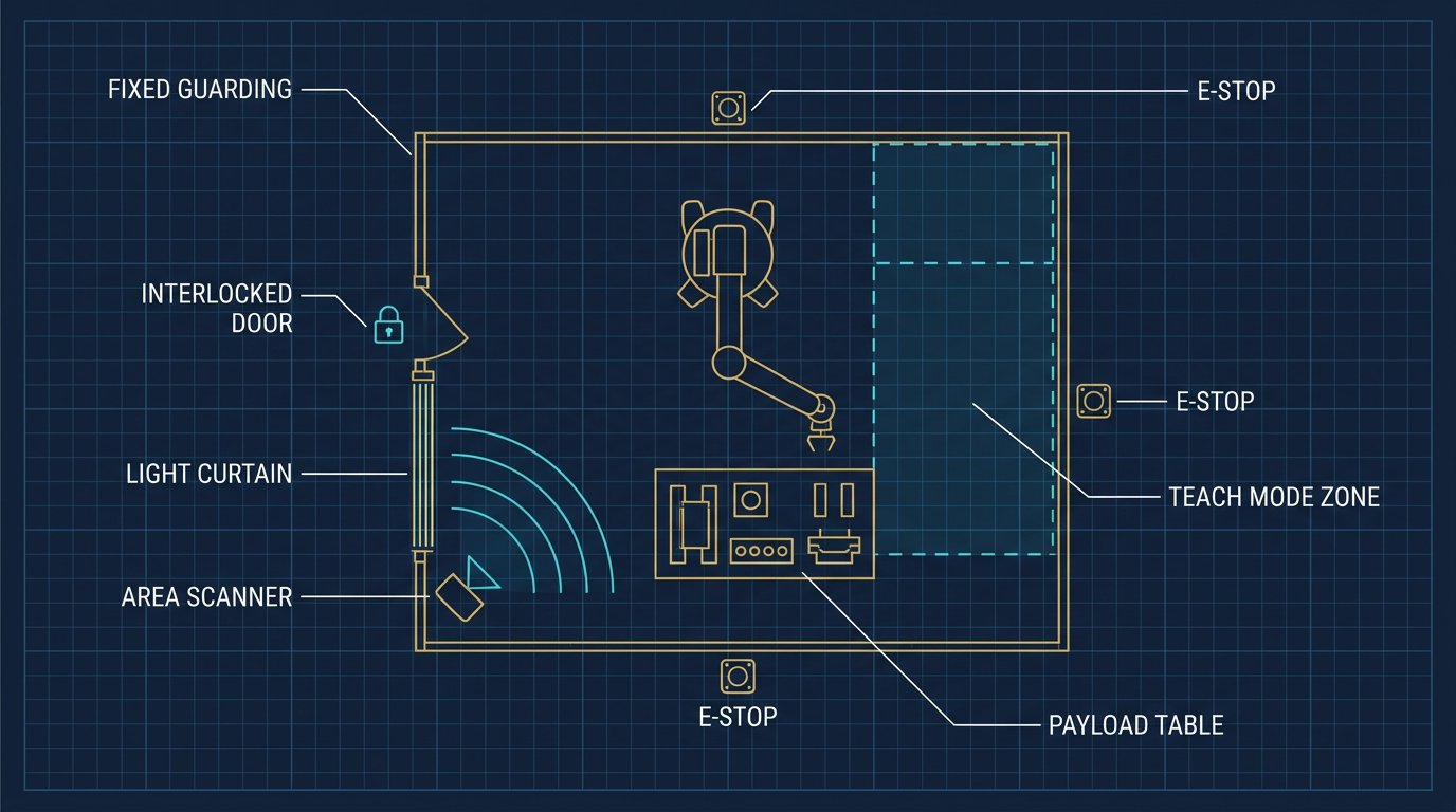
No. A light curtain is one safeguarding component within a broader safety system that must include a safety-rated stopping function, verified stopping time and distance calculations, and often complementary measures like fixed guarding on non-access sides of the cell.