The Engineering Philosophy of Robot E-Stops
Designing an emergency stop (E-stop) system for a 6-axis robot arm is not as simple as wiring a red mushroom button to the main power contactor. The goal of an E-stop is to remove the hazard as quickly as possible without introducing new, secondary hazards. For example, instantly cutting power (uncontrolled stop) to a robot holding a 50 kg payload over a conveyor could cause the arm to drop the load or slam into the floor due to gravity and mechanical backlash.
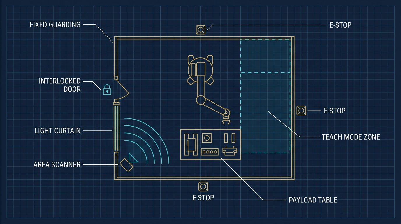
Modern industrial robot safety architecture relies on controlled deceleration, redundant safety logic, and specific stop categories defined by international standards. In North America, these designs must satisfy ANSI/RIA R15.06 (USA), CSA Z434 (Canada), and the fundamental electrical safety rules of IEC 60204-1.
An E-stop must remove the hazard without creating a new one. Instant power removal is rarely the safest option for a high-inertia 6-axis arm.- Robotics Engineering, Safety Architecture Team
Stop Categories: 0, 1, and 2
IEC 60204-1 and ISO 10218-1 define three distinct stop categories. Understanding when to apply each is the foundation of robot safety design.
| Stop Category | Action | Power After Stop | Typical Robot Application |
|---|---|---|---|
| Category 0 | Immediate power removal (uncontrolled) | Disconnected | Only used if Category 1 fails; risks payload drop or axis drift |
| Category 1 | Controlled deceleration to zero, then power removal | Disconnected | Standard industrial robots (welding, material handling) |
| Category 2 | Controlled deceleration to zero, power maintained | Maintained (STO active) | Collaborative robots (cobots), quick restart cycles |
For most industrial 6-axis arms, a Category 1 stop is the default E-stop behavior. The robot uses its servo drives to brake the axes in a controlled manner (typically achieving zero velocity in under 500 milliseconds), at which point the safety circuit drops the main power contactors. Category 0 (power removal in under 250 ms) is generally reserved as a secondary,硬件 backup if the controlled stop fails.
Circuit Architecture: Dual-Channel Redundancy
Safety circuits cannot rely on a single wire or a single relay. If a wire breaks or a contact welds, the E-stop must still function. This is achieved using dual-channel architecture.
An E-stop button contains two sets of normally closed (NC) contacts. When the button is pressed, both contacts open simultaneously. The signals from both channels are fed into a safety monitoring device—typically a safety relay (like a Pilz PNOZ) or a Safety PLC (like an Allen-Bradley GuardLogix). The safety device performs a cross-fault diagnosis every controller cycle (often 1–10 ms) to ensure both channels match. If Channel A reads "open" but Channel B reads "closed," the safety device detects a fault and immediately forces the robot into a safe state.
This architecture must meet a specific Performance Level (PL) as defined by ISO 13849-1. For robot cells in the USA and Canada, PL d (Category 3) is the minimum requirement, meaning the circuit can detect a single fault and still perform the safety function. High-risk applications often require PL e (Category 4), where faults are detected before the next safety demand occurs.
Safe Torque Off (STO) Integration
Historically, achieving a Category 0 or Category 1 stop required physically dropping electromechanical contactors in the power lines between the drive and the motor. Modern servo drives now feature STO (Safe Torque Off), a silicontegrated safety function.
When the safety relay triggers STO, it sends a 24V signal to the drive that disables the PWM switching of the power transistors. The motor can no longer generate torque, causing it to coast to a stop. Because STO is a certified safety function (SIL 3 / PL e), it eliminates the need for bulky power contactors in Category 2 applications. For a Category 1 stop, the drive uses its standard control loop to decelerate the motor to zero speed, and then STO is activated to maintain the safe state without mechanical wear.
Hardware Selection: Safety Relays vs. Safety PLCs
Choosing between a dedicated safety relay and a Safety PLC depends on cell complexity:
- Safety Relays: Cost-effective and simple for single-zone cells. If a cell has one robot, one E-stop, and one light curtain, a standard dual-channel safety relay is sufficient. Wiring is hardwired and logic is fixed.
- Safety PLCs: Required for complex, multi-zone cells. If a cell has multiple area scanners, interlocked gates with muting, and conditional logic (e.g., Robot A can run while Operator B is in Zone 1, but Robot B must stop), a Safety PLC is necessary. It allows programmable logic while maintaining PL e certification.
Implementation and Compliance Checklist
- Conduct a Risk Assessment: Do not specify safety hardware without first determining the required Performance Level (PLr) based on hazard severity, exposure frequency, and avoidance possibility.
- Map Stop Categories: Define which faults trigger which stop. An operator opening a gate might trigger Category 2 (pause and maintain position), while hitting the E-stop triggers Category 1 (stop and cut power).
- Verify Response Times: Ensure the total stopping time (sensor response + safety relay processing + drive STO execution + mechanical braking) is within the cell's safety calculation.
- Design for Recovery: An E-stop must latch mechanically. The circuit cannot be reset simply by closing the contact; an operator must physically twist/pull the button to release it, and then press a deliberate, separate reset button.
- Validate Software Limits: Ensure the robot's internal safe operating limits (e.g., DCS on FANUC, Safe Operation on KUKA) are integrated into the external safety chain, not just the standard controller logic.
Related Resources
- Area Scanner Setup for Robot Arms: 3D Safety Monitoring & Interlocks
- Integrating Light Curtains with 6-DOF Robot Arms: Safety Zones & Setup
- Robot Arm Risk Assessment Template for USA and Canada Facilities
- Integrating 6-Axis Robot Arms with Siemens and Allen-Bradley PLCs
- The Complete 6-DOF Robot Arm Guide (2026)
Sources and Methodology
Technical parameters in this guide (e.g., 250 ms power removal, 500 ms controlled stop, dual-channel diagnosis timing) are drawn from IEC 60204-1 (Electrical Equipment of Machines) and manufacturer safety guidelines (Pilz, Allen-Bradley, SICK). Compliance frameworks reference ANSI/RIA R15.06, CSA Z434, ISO 10218-1, and ISO 13849-1. Always validate your safety architecture with a site-specific risk assessment and a certified safety engineer.
What is the difference between Stop Category 0 and Stop Category 1 for robots?
Stop Category 0 immediately removes power to the robot motors without a controlled ramp-down, causing an abrupt stop. Stop Category 1 executes a controlled deceleration using the servo brakes and drives, and only removes power after the robot has reached zero velocity. Category 1 is generally preferred for industrial robots to prevent mechanical damage or tool ejection.
What is Safe Torque Off (STO) in a robot safety circuit?
Safe Torque Off (STO) is a safety function integrated into modern servo drives. When triggered, it prevents the drive from generating the torque needed to rotate the motor, effectively stopping motion without physically cutting the main power contactors. This allows for faster restart times and less mechanical wear compared to a hard power cut.
Do I need a safety relay or a safety PLC for a robot E-stop circuit?
For a single, simple robot cell with basic E-stops and gate switches, a dedicated safety relay (like a Pilz PNOZ) is sufficient and cost-effective. For complex cells with multiple safety zones, area scanners, and conditional logic, a Safety PLC (like an Allen-Bradley GuardLogix) is required to manage the interdependencies safely.