Why the Wrist Joint Gets a Different Gearbox Than the Base
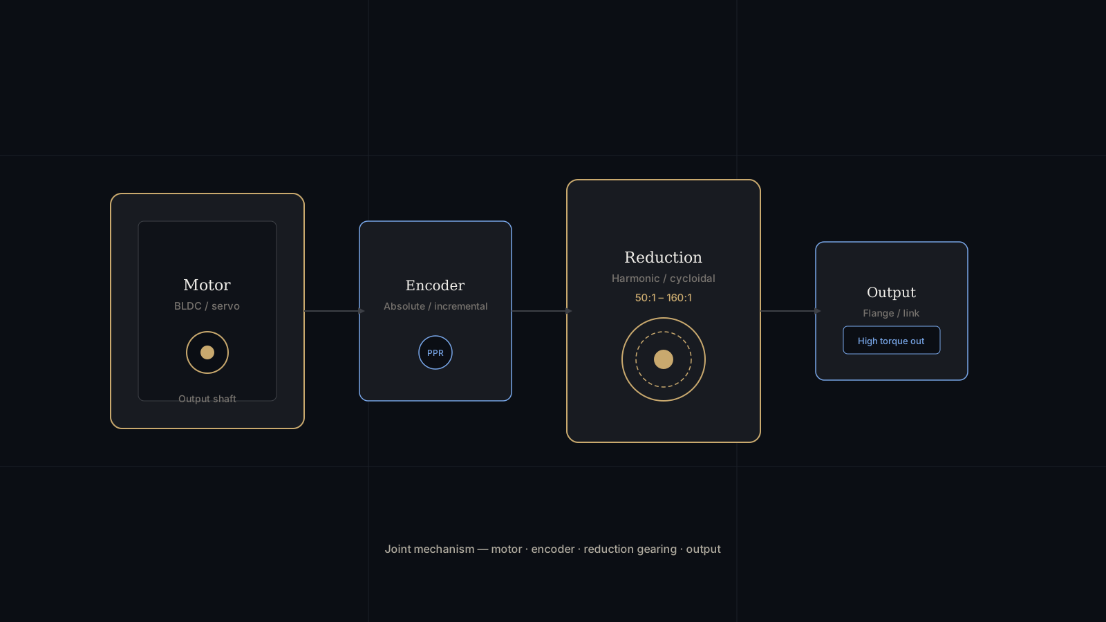
Open the joints of almost any 6-axis industrial or collaborative arm and you'll find two different families of speed reducer doing two different jobs. The base and shoulder, where torque and shock loading are highest, are frequently built around cycloidal reducers. The wrist — joints 4, 5, and 6, where the priority shifts from raw torque to compactness, low backlash, and precise, repeatable positioning — is where strain wave gearing, commonly known by the trademark Harmonic Drive, tends to dominate. This isn't a marketing distinction; it comes directly from how the mechanism is built, and understanding it changes how you size and select a joint.
This guide covers what a harmonic drive actually is, the reduction-ratio math behind it, the specification categories that matter when comparing components, the real limitations engineers run into (lost motion, fatigue life, radial load capacity), and how it stacks up against planetary and cycloidal alternatives for a 6-DOF arm.
The Mechanism: Three Parts, One Elastic Trick
A strain wave gear set has three main components, and the entire principle rests on deliberately flexing one of them:
- Wave generator — an elliptical cam wrapped in a thin-section ball bearing. It's the input: whatever motor or input shaft drives the joint connects here.
- Flexspline — a thin-walled, cup-shaped steel component with external gear teeth cut around its open rim. It is flexible by design — thin enough that the elliptical wave generator can deform it into an oval shape when inserted inside it.
- Circular spline — a rigid, solid ring with internal gear teeth, sized to surround the flexspline. It has slightly more teeth than the flexspline, almost always by exactly two.
When the wave generator rotates inside the flexspline, it forces the flexspline's teeth to fully engage the circular spline's teeth at the two points along the ellipse's major axis, while the teeth at the minor axis (90° away) are completely disengaged. As the wave generator keeps turning, this zone of engagement sweeps continuously around the circumference. Because the flexspline has fewer teeth than the circular spline, it can't complete a full rotation in step with the circular spline — each full turn of the wave generator advances the flexspline by exactly the tooth-count difference, in the opposite rotational direction. That's the entire reduction mechanism: no separate gear stages, no planet carriers, just one elastic deformation cycle per input revolution.
i = Zflexspline / (Zcircular spline − Zflexspline)
Worked example — a flexspline with 200 teeth and a circular spline with 202 teeth (a 2-tooth difference, typical of a single-lobe wave generator):
i = 200 / (202 − 200) = 200 / 2 = 100:1
This is why a single strain-wave stage can reach ratios that would need two or three stages of planetary gearing — the entire reduction comes from a 2-tooth difference acting over one full input revolution, not from cascading gear meshes.
Because engagement is spread across an arc of the gear (not a single tooth pair at a time, as in a spur or helical gear), and because the flexspline is deliberately preloaded against the circular spline by the wave generator, tooth-to-tooth backlash is effectively eliminated. That's the source of the "zero backlash" claim — but it comes with an important asterisk covered below.
The Asterisk: Lost Motion Is Not the Same Thing as Zero Backlash
Because the flexspline is a thin elastic shell rather than a rigid gear body, applying torque to the output twists it slightly before the gear teeth themselves take up any slack. Manufacturers characterize this with a torsional stiffness curve that has three distinct regions: a low-stiffness region near zero output torque, a transition region, and a higher, roughly linear-stiffness region as torque approaches the rated value. The small angular deflection in that near-zero-torque region — often called lost motion or hysteresis loss — is what actually limits positioning precision in a servo loop, not tooth backlash, which is genuinely close to zero.
In practice this matters most when a joint reverses direction or operates near zero load: the controller can command a small angular move and see little to no output motion until the elastic windup is taken up. Precision-grade harmonic drive components typically hold this lost motion under roughly 1 arc-minute, but it is a real, specified number you should pull from the manufacturer's datasheet — not an assumption that "zero backlash" means zero compliance.
Specification Categories That Actually Matter
When comparing harmonic drive components or gearheads for a joint design, these are the parameters worth lining up side by side — not a generic robot-arm payload table, but the numbers specific to the reducer itself:
| Parameter | What it tells you | Typical range (component sets) |
|---|---|---|
| Reduction ratio | Single-stage ratio available in a catalog series | ~30:1 to 160:1, with some specialty series extending higher |
| Lost motion / hysteresis | Angular deflection near zero torque — the real precision limit | Roughly 1 arc-minute or less for precision grades |
| Rated output torque | Continuous torque the flexspline can sustain at rated life | Scales with frame size; consult the specific series datasheet |
| Repeated peak torque | Torque allowed briefly and repeatedly (e.g. acceleration spikes) | Commonly around 2× rated torque |
| Momentary max torque | Non-repeated shock rating (e.g. a collision event) | Commonly 3× rated torque or higher, series-dependent |
| Efficiency | Mechanical efficiency at rated conditions | Roughly 60–90%, falling off at low torque and high ratio |
| Service life | Fatigue-limited life of the flexspline at rated torque | Often quoted around 10,000+ hours at rated load; drops sharply above it |
Two things worth flagging explicitly because they're easy to miss when sizing a joint: efficiency is not constant. It falls at partial load and at higher reduction ratios, because a meaningful share of the input energy goes into cyclically flexing the flexspline rather than into output torque — this matters for motor sizing and thermal budgeting, especially in a joint that dithers near zero torque for long periods. And the momentary torque rating exists specifically to absorb short shock events like a collision or a hard stop, not sustained operation — running near that number continuously will consume fatigue life far faster than the rated hours figure implies.
What a Bare Component Set Cannot Do By Itself
A wave generator, flexspline, and circular spline sold as a component set are not designed to directly carry radial loads, axial loads, or moment loads on the output — the flexspline's thin walls simply aren't built for it. This is why two different product formats exist in practice:
- Component sets — the three core parts only, intended to be integrated into a housing you design yourself, with your own output bearing support.
- Unit-type gearheads — the same strain-wave core, but pre-integrated with a cross-roller output bearing and a housing, so the output flange can directly carry the next robot link's radial, axial, and moment loads without a separate bearing stage.
For a robot wrist joint, the unit-type format is almost always the practical choice — it's what lets a harmonic drive act as a compact, self-contained joint rather than one component in a larger custom bearing assembly.
Harmonic Drive vs. Planetary vs. Cycloidal: A Real Comparison
None of these three reducer types is universally "better" — they solve different parts of the joint-design problem, which is exactly why a single 6-DOF arm often uses more than one type across its own joints.
| Characteristic | Harmonic (strain wave) | Planetary | Cycloidal (e.g. Nabtesco RV-type) |
|---|---|---|---|
| Single-stage ratio | High (tens to low hundreds : 1) | Low (typically single digits to ~10:1 per stage) | High, comparable to harmonic |
| Backlash / lost motion | Near-zero tooth backlash; small elastic lost motion | Noticeable unless specifically preloaded (adds cost) | Very low, often lower than harmonic under load |
| Shock / overload tolerance | Comparatively limited — flexspline is a fatigue-critical part | Good — conventional rigid gear teeth | Excellent — a defining strength of the cycloidal principle |
| Radial/axial load capacity (bare component) | Low — needs external or integrated bearing support | Moderate, depends on carrier design | High — commonly rated to carry substantial external loads directly |
| Efficiency | Moderate, drops at partial load | High (often 90%+ per stage) | Good, generally more consistent under load than harmonic |
| Size / weight for a given ratio and torque | Very compact | Larger for equivalent single-stage ratio | Compact but typically heavier than harmonic for the same envelope |
| Typical placement in a 6-DOF arm | Wrist joints (4, 5, 6) | Lower-torque axes, cobots, some full builds | Base, shoulder, elbow — high-torque, high-shock axes |
The pattern that shows up across most commercial industrial arms follows directly from this table: cycloidal reducers absorb the base and shoulder, where a dropped payload or a hard stop against a fixture can send a large shock load straight through the joint, and where the reducer also has to carry real radial and moment loads from the arm's own weight. Harmonic drives take over at the wrist, where the loads are smaller, the priority is precision and compactness, and the joint is less likely to see a severe shock event. Collaborative robots, with generally lower payloads throughout, often lean on harmonic drives across more of the arm for exactly the compactness and low-lost-motion reasons described above.
"Zero backlash" describes the gear mesh, not the joint. A servo controller still has to account for the flexspline's own elastic windup near zero torque — that's a control problem, not a manufacturing defect.— Robotics Engineering, on strain wave gear characterization
Selection Checklist for a Wrist Joint Design
Before specifying a strain wave gear set or gearhead for a joint, work through these in order — sizing backwards from torque alone is the most common mistake:
- Define the duty cycle, not just peak torque. Continuous rated torque, repeated peak torque, and momentary (shock) torque are three different numbers on the datasheet. Confirm which one your worst-case motion profile actually hits, and how often.
- Check lost motion against your positioning tolerance. If the joint needs to hold a tight repeatability spec through direction reversals, the hysteresis figure — not the advertised ratio — is often the binding constraint.
- Decide component set vs. unit-type gearhead early. A component set needs your own cross-roller or angular-contact bearing design around it; budget real engineering time for that if you go this route instead of a pre-integrated unit.
- Model efficiency at your actual operating point, not just rated load. If the joint spends significant time at partial torque, use the efficiency curve at that point for motor and thermal sizing, not the single headline efficiency figure.
- Size fatigue life to real usage, including shock events. Occasional operation near momentary torque (collisions, hard stops) draws down flexspline fatigue life faster than continuous rated-torque operation — factor this in if the application involves frequent contact.
- Confirm interface compatibility. Output flange dimensions on robot-oriented gearheads commonly follow ISO 9409-1 robot flange patterns — verify this against your link and end-effector mounting design before committing to a part number.
Where to Verify Real Numbers
The ranges in this guide are representative of strain wave gearing as a technology, not a substitute for a specific manufacturer's datasheet. Reduction ratio, torque ratings, lost motion, and life figures vary meaningfully between series and frame sizes, and pricing for these components is typically quote-based rather than listed, since it depends on ratio, frame size, and integration format. Before finalizing a joint design, pull the current datasheet directly from the manufacturer:
- Harmonic Drive LLC — North American manufacturer of component sets and unit-type gearheads for robotics and precision motion.
- Harmonic Drive SE — the original German manufacturer of strain wave gearing, with an extensive robotics-oriented product line.
- Nabtesco — the dominant supplier of cycloidal (RV-type) reducers used at the base and shoulder joints of many industrial arms, useful as a direct comparison point.
- Wittenstein — manufactures both strain wave and high-precision planetary gearing, with published comparison data between the two families.
For gear-design standards referenced when specifying custom housings or verifying tooth geometry, AGMA publishes the relevant gearing standards for the North American market.
Frequently Asked Questions
Is a harmonic drive really backlash-free?
Not in the strict sense. Tooth backlash is essentially eliminated by preloading the flexspline against the circular spline, but the flexspline is a thin elastic cup, so there is still a small torque-dependent windup called lost motion or hysteresis loss, typically under 1 arc-minute in precision grades. It behaves differently from mechanical backlash and needs to be accounted for separately in a servo control loop.
Why do so many robot arms use harmonic drives in the wrist but not the base?
Harmonic drives are compact and lightweight for a given reduction ratio and offer very low lost motion, which suits the lower-torque, precision-critical wrist axes. They are comparatively less tolerant of shock loading and radial/axial forces than cycloidal reducers, so many industrial arms use cycloidal gearing at the base and shoulder, where torque and shock loads are highest, and reserve harmonic drives for the wrist.
What limits the life of a harmonic drive?
The flexspline is cyclically deformed on every input revolution, so it is a fatigue-limited component rather than a wear-limited one in the way a spur gear is. Manufacturers rate service life in hours or input revolutions at a given output torque, and that rating drops sharply if the joint is regularly operated above its rated torque or subjected to repeated shock loads near its momentary limit.
Can a harmonic drive support the output shaft directly, or does it need a separate bearing?
A bare component set has very limited capacity to carry radial, axial, or moment loads on its own and needs external bearing support. This is why robot-oriented unit-type harmonic gearheads integrate a cross-roller output bearing, letting the output flange mount directly to the next link without a separate support bearing.
Primary sources and further reading
These references support the general engineering concepts in this guide. Confirm every safety-relevant limit in the current documentation before you rely on it.
Links checked: August 5, 2026.