Why Vacuum Grippers Dominate High-Speed Pick-and-Place
Vacuum End-of-Arm Tooling (EOAT) is the standard solution for handling smooth, flat, or semi-porous objects across consumer goods, automotive glass, and electronics assembly. Unlike mechanical parallel grippers that require physical clearance around a part's perimeter, vacuum cups interface directly with the top surface. This allows high-density packing, box depalletizing, and part transfer without modifying fixture spacing.
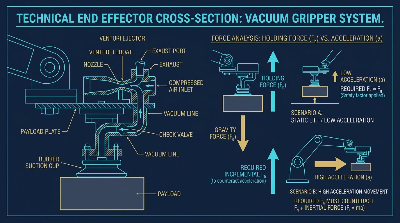
However, an effective vacuum system requires more than mounting rubber cups to an aluminum profile. Engineers must calculate theoretical holding forces against dynamic robot acceleration, manage internal line restrictions, and select the correct vacuum generation architecture.
Vacuum gripping is atmospheric clamping: atmospheric pressure holds the workpiece against the cup when negative pressure is established inside.- Robotics Engineering, Pneumatic Automation Division
Theoretical vs. Dynamic Holding Force Calculations
The holding force generated by a vacuum cup is governed by the pressure differential (ΔP) between atmospheric pressure and the internal vacuum level, multiplied by the cup's effective surface area (A):
F = ΔP × A
For example, a 40 mm diameter suction cup has an effective area of roughly 12.57 cm² (0.001257 m²). Operating at a typical industrial vacuum level of -0.7 bar (70 kPa below ambient), the theoretical vertical holding force is approximately 88 N (equivalent to roughly 9 kg of static mass at sea level).
Applying Dynamic Safety Factors
In high-speed 6-axis robot motion, static calculations are insufficient. When the arm accelerates laterally or rotates its wrist (J4, J5, J6), the workpiece experiences both shear forces and centrifugal forces. Engineers apply strict safety factors (S):
- Horizontal Lift, Low Acceleration ( < 1g ): Safety factor S = 2.0.
- Vertical Lift or High Acceleration ( > 1g ): Safety factor S = 4.0 or higher. Shear friction between the cup lip and the part surface is typically only 0.1 to 0.4 of the normal force, making slippage the primary failure mode.
Vacuum Generation: Decentralized Venturi vs. Electric Pumps
Selecting the vacuum generator impacts robot payload, response time, and energy efficiency. The two primary technologies used in 6-DOF robot cells are decentralized Venturi ejectors and electric vacuum blowers.
| Generator Type | Operating Principle | Best Application Fit | Key Trade-off |
|---|---|---|---|
| Decentralized Venturi (Piab COAX) | Compressed air expansion | High-speed sheet metal, packaging | Consumes continuous compressed air (~20 L/min) |
| Electric Vacuum Pump (Schmalz ECBPM) | Integrated 24V DC motor | Autonomous mobile robots (AMRs), cobots | Higher mass on the wrist; lower peak vacuum flow |
| Multi-Stage Ejector (Festo OVEM) | Cascaded Venturi nozzles | Porous materials (cardboard, raw wood) | Requires larger pneumatic feed tubing |
For high-speed industrial robots, decentralized Venturi ejectors mounted directly on the tool flange are preferred. Minimizing the hose length between the ejector and the suction cup eliminates pneumatic line latency, reducing the time required to build full vacuum down to 0.05–0.15 seconds.
Suction Cup Geometry and Material Selection
Matching the cup material and shape to the workpiece prevents dropouts and surface marking:
- Flat Cups: Offer high rigidity and minimal internal volume, resulting in the fastest evacuation times and the greatest resistance to shear forces during high-speed lateral motion. Ideal for flat steel, glass, and smooth plastic.
- 1.5 to 2.5 Bellows Cups: The accordion folds provide vertical compliance, allowing the cup to adapt to curved surfaces or height variations on a conveyor. However, bellows cups can buckle under high lateral acceleration.
- Cup Materials: Nitrile (NBR) is cost-effective and oil-resistant for metal stamping; Silicone (VMQ) handles extreme temperatures and food-grade tasks but can leave microscopic residues on glass or painted surfaces; Polyurethane (Elastodur) provides maximum wear resistance in high-abrasion applications.
Cycle Time Optimization: The Blow-Off Pulse
In high-throughput pick-and-place cells, the release phase can become a bottleneck. Simply shutting off the compressed air to a Venturi ejector leaves residual vacuum inside the suction cup, causing the workpiece to cling for 200–500 ms after the command is sent.
To achieve instantaneous release, industrial vacuum systems use an active blow-off pulse. When the drop command is executed, a small valve injects a brief burst of positive pressure (0.2–0.5 bar) into the cup cavity, equalizing pressure with the atmosphere in under 0.05 seconds. This allows the robot to immediately retract without dragging the part.
Implementation Checklist for Robot Cell Builders
- Calculate Total EOAT Weight: Include the mounting plate, manifolds, ejectors, sensors, and suction cups. Subtract this total from the robot's rated payload to determine maximum part capacity.
- Minimize Pneumatic Tube Length: Mount the vacuum ejector and blow-off valve as close to the cups as possible. Every meter of hose adds dead volume and delays cycle response.
- Install Digital Vacuum Switches: Never program blind pick timers. Use a digital pressure sensor with an adjustable threshold (e.g., confirming -0.65 bar) before initiating robot arm motion.
- Account for Surface Porosity: When handling corrugated cardboard or raw wood, vacuum levels will drop due to leakage. Size the generator for high suction flow rate (L/min) rather than ultimate vacuum level.
Related Resources
- Gripper Design Guide for 6-DOF Robot Arms: Vacuum, Magnetic & Mechanical
- Magnetic Gripper Design for 6-Axis Robot Arms: Ferrous Handling
- Cooling Systems for High-Payload 6-Axis Robot Arms
- Integrating Light Curtains with 6-DOF Robot Arms: Safety Zones & Setup
- The Complete 6-DOF Robot Arm Guide (2026)
Sources and Methodology
Technical data in this guide (e.g., -0.7 bar operating vacuum, 20 L/min air consumption benchmarks, safety factors) reflect industrial automation standards and technical documentation from manufacturers including Piab, Schmalz, and Festo. Mechanical safety considerations reference ISO 12100. Always verify holding force calculations on actual production samples to account for surface finish and porosity variations.
What is the difference between a Venturi ejector and an electric vacuum pump on a robot arm?
A Venturi ejector uses compressed plant air to create vacuum locally right at the robot wrist, offering rapid response times and very low weight, but consuming continuous compressed air. An electric vacuum pump uses a motorized blower or vane pump, making it ideal for mobile robots (AMRs) or facilities where compressed air is unavailable.
How do you size suction cups for high-acceleration robot pick-and-place?
Theoretical holding force is calculated using F = ΔP × A. However, for dynamic robot motion, engineers apply a safety factor of 2.0 for horizontal lifts with low acceleration, and 4.0 or higher for vertical lifts where shear forces act across the cup during rapid acceleration and deceleration.
Why is a blow-off pulse necessary for vacuum grippers?
When a vacuum valve closes, residual negative pressure inside the suction cups and pneumatic hoses can cause parts to stick for several hundred milliseconds. An active blow-off pulse injects a brief burst of positive compressed air into the cups, breaking the vacuum immediately and reducing release cycle time down to 0.05–0.1 seconds.
Primary sources and further reading
These references support the general engineering concepts in this guide. These figures are orientation only — the manufacturer’s current documentation governs.
Links checked: August 5, 2026.