What this guide covers
The short answer: how should robot-arm cables be routed?
Use the simplest cable path that survives the complete range of motion. For a small educational arm, an external sleeve with generous bend loops may be sufficient. For a compact machine, internal channels can protect wiring and improve appearance. For a production arm with repeated motion, use continuous-flex cables, engineered strain relief, validated bend radius and a documented replacement procedure.
A slip ring is not a general-purpose cable organizer. It is an electromechanical interface for transferring power or signals across a rotating joint. Use one when a joint must rotate continuously and a cable would otherwise twist beyond its limit. If the joint only moves through a limited angle, a properly sized service loop may be cheaper and easier to maintain.
The most common failure is not a dramatic cable break. It is an intermittent encoder, communication or safety signal caused by repeated flexing, an over-tight tie, a connector that carries mechanical load or a cable that violates its dynamic bend radius.
What a robot-arm cable system must survive
Robot cabling experiences a different environment from stationary control-panel wiring. The cable can bend thousands or millions of times, twist around a wrist axis, rub against a printed cover, accelerate with the link and heat up near motors or weld equipment. A pneumatic hose can also kink or fatigue while its fittings see side loads.
- Bending: repeated flexing around a defined radius changes the conductor and insulation stress.
- Torsion: twisting a cable bundle is different from bending it and may require a torsion-rated construction.
- Pulling: the connector should not carry the weight or acceleration of the bundle.
- Abrasion: rubbing against a frame, drag-chain separator or sleeve can wear the jacket.
- Heat and chemicals: welding spatter, coolant, oil, UV and cleaning agents require compatible jackets.
- Electrical noise: motor power and switching currents can disturb encoder, Ethernet, analog and safety signals.
Define the duty cycle before choosing a cable. Ten slow movements per day is not equivalent to continuous six-axis production. Record joint angle, speed, acceleration, bend radius, twist, temperature and contamination so that the selected cable system matches the real application.
Internal routing versus external routing
Internal routing
Internal routing places cables through hollow links or protected channels. It reduces snagging, improves the work envelope and can protect wiring from abrasion. The disadvantages are reduced access, difficult replacement and the risk of creating a sharp bend at an entry or exit. Every internal passage needs rounded edges, a replaceable grommet and a way to inspect or pull a replacement harness.
External dress packs
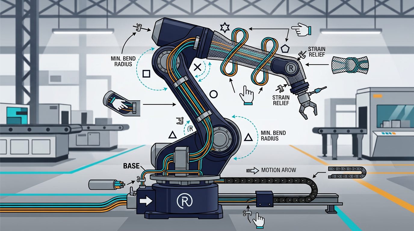
A dress pack uses a flexible conduit, braided sleeve, clamps and strain relief outside the arm. It is easier to inspect and modify when the tool changes. Use a controlled service loop rather than a loose bundle that can catch on the workspace. The loop must be tested at every joint angle, including the worst-case combination of shoulder, elbow and wrist positions.
Drag chains
A drag chain, or energy chain, constrains cables to a repeatable bend radius. Select the chain by inner height, width, allowable fill, radius, travel, speed and mounting method. Do not fill every available space: cables need room to move and should not be forced against separators. The chain's bend radius must be compatible with the largest cable or hose inside it.
| Method | Advantages | Risks and limits | Best fit |
|---|---|---|---|
| Internal channel | Protected, compact, clean envelope | Harder service and inspection | Compact prototypes and enclosed joints |
| External dress pack | Accessible and easy to change | Can snag or rub if poorly restrained | Production tools with frequent changes |
| Drag chain | Controlled radius and organized motion | Needs correct fill and mounting | Linear axes and predictable articulation |
| Slip ring | Allows continuous rotation | Contact wear, noise and circuit limits | Continuous-rotation base or wrist |
Slip rings and continuous rotation
A slip ring transfers electrical power or signals between a stationary side and a rotating side. It commonly contains conductive rings, brushes or contact elements, insulation and a housing. Some designs add Ethernet, fiber-optic or fluid rotary unions, but these functions should not be assumed from the word "slip ring" alone.
How to specify one
- Circuits: count power, ground, encoder, Ethernet, analog, digital and shield paths separately.
- Electrical rating: check current and voltage per circuit, including inrush and fault conditions.
- Signal quality: verify bandwidth, contact resistance, insulation resistance and shielding for data.
- Speed and rotation: specify continuous speed, direction reversals and allowable rotation angle.
- Mechanical load: do not use the slip-ring shaft or housing as a structural bearing unless rated for that load.
- Environment: check IP rating, temperature, dust, coolant, vibration and installation orientation.
- Life: use the manufacturer's life test conditions; a cycle rating is meaningful only when speed and load are comparable.
Ethernet through a contact-based slip ring may need a purpose-designed module and careful cable termination. High-speed differential signals are sensitive to impedance discontinuity, contact noise and shielding. If a joint only needs limited travel, retaining a cable loop can avoid these signal-integrity issues.
Selecting cables, hoses and connectors
Dynamic cable versus flexible cable
A cable described as flexible is not automatically rated for continuous flexing. Look for a dynamic-chain, torsion, robotic or continuous-motion rating and read the test conditions. The manufacturer's minimum dynamic bend radius is the controlling value. Do not design to a smaller radius because the cable appears to fit.
Separate power and signal
Keep motor, heater, solenoid and high-current power cables separated from encoder, Ethernet, analog and safety wiring. If they must share a conduit, use physical separators and shielded cables selected for the application. Terminate shields according to the drive and control-system design; an arbitrary shield connection can create a ground loop.
Pneumatic and coolant lines
Choose hose material and fittings for pressure, temperature, chemical exposure and minimum dynamic bend radius. Prevent fittings from bending the hose at the connector. A strain-relieved hose should not pull sideways on a valve, gripper or spindle. For coolant, plan for leaks and provide a route that keeps fluid away from electrical connectors.
Connectors and service loops
Use locking connectors with the required current, voltage, IP and vibration ratings. Leave enough service length to replace a connector without replacing the entire harness, but do not create a loop that can enter the robot's pinch zone. Mark both ends of every cable and document connector pinout, shield, spare cores and replacement part number.
Cable-routing design method
- Map the envelope: create a CAD or physical model of every joint at its minimum and maximum angle.
- List all services: motors, brakes, encoders, Ethernet, safety, gripper power, pneumatics, vacuum and coolant.
- Set fixed points: define where the harness is anchored and where it must remain free to move.
- Apply bend-radius rules: use the largest manufacturer value in a mixed bundle and account for movement, not just assembly shape.
- Add strain relief: clamp the jacket or use a rated boot close to each connector.
- Separate noisy circuits: place power and data in different paths where practical.
- Check twist: rotate each wrist through its full path and mark the harness to observe torsion.
- Test the worst pose: move slowly through combined joint limits while watching for rubbing, tension and pinching.
- Document service: photograph the route, label connectors and record inspection points.
Do not tighten ordinary cable ties directly around a dynamic cable bundle. A tie that creates a hard pressure point can reduce flex life. Use smooth clamps, hook-and-loop straps or cable-management hardware intended for motion.
Bend radius, twist and cable fill
The bend radius is measured from the centerline of the cable to the center of the bend. A cable manufacturer may specify separate values for fixed installation and dynamic motion. The dynamic value is the one that matters inside a drag chain or moving arm. If several cables have different values, use the largest value or separate the cables into suitable paths.
Drag-chain fill should be planned by cross-sectional area and movement. Cables should not be packed so tightly that they cannot change position, and heavy cables should not crush smaller signal cables. Use separators when power, data and hoses need controlled spacing. Verify that the chain does not twist or buckle at its mounting points.
Inspection, testing and maintenance
Inspect the harness at commissioning and at an interval based on duty cycle. Look for jacket polishing, flat spots, cracks, exposed braid, loose clamps, connector movement, hose kinks and unexpected changes in motor or encoder behavior. A thermal camera or voltage measurement can help locate a high-resistance connection, but it does not replace mechanical inspection.
- Move the arm slowly through the full envelope with power isolated from the tool where safe.
- Check continuity and insulation only with methods compatible with connected electronics.
- Monitor encoder errors, communication retries, safety faults and intermittent tool resets.
- Measure bend and twist at the most demanding joint rather than at the easiest-to-reach section.
- Replace a damaged cable instead of wrapping a moving failure point with tape.
For a slip ring, trend contact resistance, signal errors, temperature and rotation count where possible. Do not clean contacts with an unapproved solvent or open a sealed unit without the manufacturer's procedure.
Cable-management troubleshooting
| Symptom | Likely cause | What to check |
|---|---|---|
| Encoder errors at one joint angle | Cable bend, pinch or connector strain | Move slowly through the angle and inspect the harness while monitoring diagnostics. |
| Ethernet drops during wrist rotation | Signal-rated cable or slip-ring limitation | Check differential cable, shielding, termination and the slip ring's data specification. |
| Hose leaks near a fitting | Side load, excessive bend or wrong fitting | Reroute with a bend guide and replace the stressed hose section. |
| Drag chain is noisy or jerky | Overfill, wrong radius or poor mounting | Measure chain fill, spacing, alignment and the required dynamic radius. |
| Harness rubs against the arm | Missing clamp or insufficient service loop | Add a controlled restraint and retest every joint combination. |
| Slip ring signal becomes intermittent | Contact wear, contamination or overload | Review life, current, speed, environment and contact-resistance trend. |
Safety and responsible installation
Cable routing can create a new pinch point even when the robot mechanics are safe. Guard moving chains, exposed loops and rotating interfaces. Keep emergency-stop and safety circuits independent from non-safety accessories unless the complete safety design has been validated. Never assume a protective sleeve makes a cable safe to touch or prevents electrical faults.
Industrial deployment requires a risk assessment, guarding, validated stop functions and compliance with applicable standards. A six-axis prototype can use an external sleeve, but it must still be secured so it cannot catch on people, tools or surrounding machinery.
Final thoughts
Cable management is easy to underestimate because it rarely causes a dramatic, one-time failure — instead it produces the kind of intermittent encoder glitch or communication dropout that takes hours to diagnose. Treat the harness as a moving mechanical component with its own bend radius, torsion limits and service life, not as an afterthought once the joints and motors are chosen. A well-documented cable path, tested through every combination of joint limits, will save far more troubleshooting time than it costs to plan upfront.
Frequently asked questions
Should cables be routed inside a robot arm?
Internal routing can protect cables and improve the arm's envelope, but it requires sufficient space, bend relief, access for replacement and a validated motion envelope. An external dress pack is often easier to inspect and service.
What bend radius should robot cables use?
Use the cable or hose manufacturer's dynamic bend radius, not a generic rule. Dynamic applications commonly require a larger radius than stationary wiring, and repeated torsion may require a special torsion-rated cable.
When does a robot arm need a slip ring?
A slip ring is useful when a joint must rotate continuously while power or signals pass across the rotating interface. Select it by circuit count, current, voltage, signal type, speed, protection, life rating and allowable noise.
How can robot-arm cable failures be prevented?
Use suitable continuous-flex cables, correct bend radius, strain relief, separation of power and data, controlled service loops, protected connectors and a documented inspection routine. Validate the complete cable path through every joint motion.
Continue learning
For transmission and joint design, read the belt drive versus gear drive comparison and the 6-DOF Robot Arm Guide.