Collaborative robot arm assembly is not simply the installation of a smaller industrial robot beside an operator. It is the design of a complete production system in which the robot, gripper, workpiece, tooling, software and human workflow are assessed together. The best applications allocate repetitive, ergonomically difficult or highly consistent actions to the robot while the operator contributes inspection, judgment, replenishment or tasks that change frequently.
What is a collaborative robot arm assembly cell?
A collaborative assembly cell is a workstation where a robot and one or more people share a production process, and in some designs a physical workspace, under defined operating conditions. The collaboration may be sequential rather than simultaneous: the robot presents a part, pauses in a safe state, and the operator completes a joining or inspection step. Other cells use coordinated handover, machine tending or shared kitting.
This distinction matters because “collaborative” describes the intended application and safety strategy, not a universal property of a robot. A low-payload cobot fitted with a sharp tool, a heavy metal component or a high-force press operation can still create unacceptable hazards. Conversely, a conventional robot cell with appropriate safeguarding may be the better choice when speed, force or cycle time makes close human access unnecessary.
Typical assembly tasks include screwdriving, dispensing, pressing, insertion, adhesive application, pick-and-place, inspection and packaging. The automation opportunity is strongest when product variants are numerous, volumes are moderate, changeovers are frequent and ergonomic exposure is significant.
Safety functions, standards and risk assessment
Safety engineering begins with a task-based risk assessment. Document the intended use, foreseeable misuse, pinch and crush points, sharp edges, stored energy, dropped-load hazards, tool hazards, unexpected restart and access to the work envelope. The assessment should cover normal production, teaching, setup, cleaning, fault recovery, maintenance and reasonably foreseeable changes in the product or tooling.
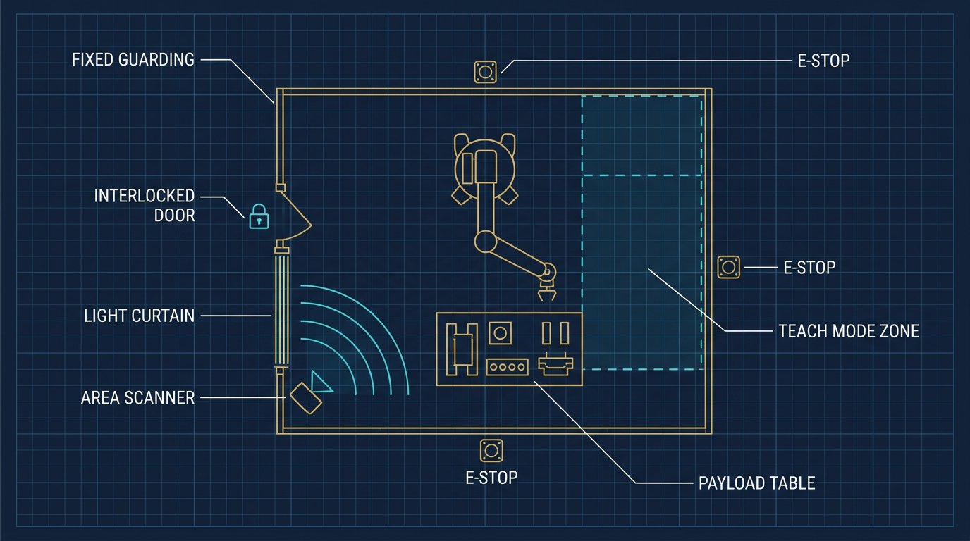
Depending on the application, collaborative operation may use power and force limiting (PFL), speed and separation monitoring (SSM), hand guiding or safety-rated monitored stop. These are different strategies. PFL limits the energy or force of contact; SSM maintains a protective separation distance using presence-sensing devices and controlled robot speed. A cell can combine collaborative modes with fixed guarding, light curtains, area scanners, interlocked doors and emergency-stop circuits.
For North American projects, engineers commonly evaluate the applicable editions of ISO 10218, ISO/TS 15066, ANSI/RIA R15.06 and CSA Z434, together with electrical, machine-safety and workplace requirements that apply in the installation's jurisdiction. Standards and legal requirements change; confirm the current edition with a qualified safety professional, standards body or certified integrator before commissioning.
Validation should include measured stopping performance, protective-device response, operating speeds, force and pressure testing where relevant, restart behavior, fault handling and verification of safety-related control functions. Record the results, residual risks, operating limits, training requirements and inspection schedule in the technical file.
Designing the cell around the human workflow
Start with the operator's complete sequence rather than with the robot model. Map every reach, lift, twist, wait state, handover and inspection action. A useful design goal is to remove high-frequency ergonomic strain without forcing the operator to work around the robot. Parts should arrive in a repeatable orientation, the robot should not block access to quality-critical features, and replenishment should be possible without entering a hazardous zone.
Recommended design sequence
- Define the product: list variants, tolerances, joining forces, surfaces that may be damaged and the acceptable defect conditions.
- Observe the manual process: record actual cycle times, walking, reaching, regrips, inspection delays and changeover losses across representative shifts.
- Divide the work: assign repeatable motion and presentation tasks to the robot, while keeping human decisions and flexible operations accessible.
- Prototype the end effector: test grip reliability, part detection, compliance, tool access, cable routing and safe failure behavior before final cell design.
- Simulate and pilot: use representative parts and operators. Measure quality, cycle time, stoppages and recovery time rather than relying on nominal robot speed.
Ergonomics should be measured alongside productivity. A robot that reduces lifting but adds awkward handovers may move the problem instead of solving it. Adjustable fixtures, height-appropriate presentation, clear status signals and a short recovery procedure often have more effect on adoption than a faster trajectory.
Robot sizing: payload, reach and repeatability
Payload is the combined mass of the gripper, fingers, sensors, cables, tool and workpiece. It is not just the weight printed on the product label. The robot must also tolerate the load's center of gravity and inertia at the most demanding orientation and acceleration. Check manufacturer load diagrams and dynamic ratings; a payload that is acceptable close to the wrist may be unsuitable at maximum reach.
| Parameter | What to calculate or verify | Why it affects assembly |
|---|---|---|
| Total payload | Tool + gripper + fingers + sensors + part | Determines motor load, acceleration and usable reach |
| Reach and workspace | Farthest pick, place, fixture and service positions | Prevents singularities, collisions and excessive joint motion |
| Repeatability | Manufacturer specification under stated conditions | Must be compatible with fixture tolerance and insertion clearance |
| Process force | Insertion, pressing, screwdriving or dispensing force | May require compliance, force sensing or a conventional guarded cell |
| Environment | Dust, washdown, temperature, ESD and cleanroom needs | Controls robot, cable, gripper and sensor selection |
Repeatability is not the same as absolute accuracy. A robot may return consistently to the same taught point while the fixture itself is displaced, the part varies, or the tool deflects. For insertion and mating operations, use datum features, chamfers, floating tooling, compliance or force control as appropriate. Confirm tolerances with a pilot rather than assuming a catalog repeatability value guarantees successful assembly.
For parts that are reflective, flexible, porous or poorly presented, vision and force feedback can improve robustness, but they introduce calibration, lighting, latency and maintenance requirements. A simple mechanical nest and presence sensor is often more reliable than an unnecessarily complex perception stack.
Cycle-time analysis and a defensible ROI model
Robot motion time is only one part of the production cycle. Include pick and place, tool actuation, settling, inspection, human handover, replenishment, robot pauses, fault recovery, changeover and planned maintenance. A useful first model is:
Calculate recovery loss as the expected frequency of a stop multiplied by the average time required to detect, clear and restart it. Then compare the automated cell with measured manual performance at the same quality level. Claims such as “15–25% faster” are not universal benchmarks: actual improvement depends on the task, operator balance, tooling, uptime, staffing and product mix.
ROI checklist
- Capital cost: robot, controller, gripper, tooling, fixtures, safety devices, vision, electrical work and integration.
- Implementation cost: engineering, programming, validation, documentation, training and production downtime during installation.
- Recurring cost: maintenance, consumables, calibration, spare parts, software support and energy.
- Benefits: measured labor reallocation, reduced ergonomic exposure, quality improvement, throughput and avoided downtime.
- Constraints: utilization, staffing model, product changeovers, ramp-up time and the cost of unresolved exceptions.
Use a sensitivity analysis for utilization, labor rate, uptime and demand. A pilot should report best case, expected case and downside case. This produces a more credible investment decision than multiplying a nominal robot cycle by the number of shifts.
Controls, tooling and commissioning
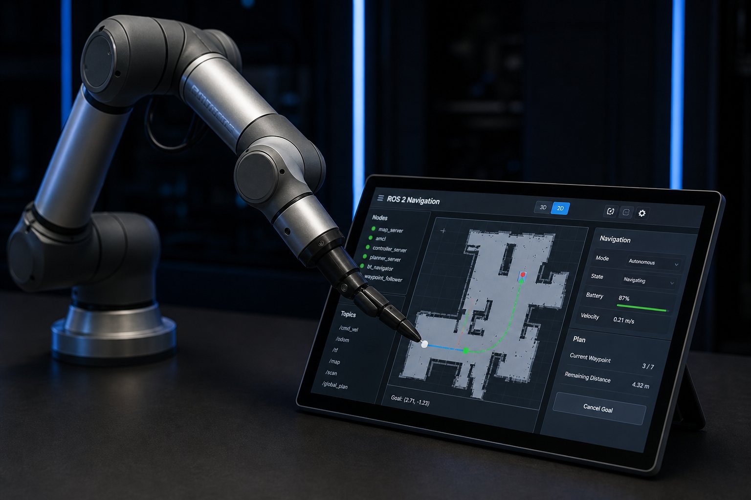
A dependable cell needs clear interfaces between the robot controller, PLC, safety system, sensors, tooling and production software. Industrial Ethernet protocols such as EtherNet/IP, PROFINET or EtherCAT may be relevant depending on the selected equipment. ROS 2 can be valuable for research, perception and flexible orchestration, but production teams should also evaluate deterministic behavior, safety certification, lifecycle support, diagnostics and who will maintain the system.
End-effectors deserve the same engineering attention as the arm. Include gripper confirmation, part-present sensing, vacuum monitoring where applicable, tool-change detection, cable bend radius and a defined response to loss of air or power. For screwdriving and dispensing, monitor torque, depth, pressure or flow so the system can detect a process failure instead of merely completing a motion.
Commissioning checklist
- Verify mechanical mounting, fixture datum, fasteners, cable routing and tool clearances.
- Calibrate TCP, work objects, cameras, force sensors and external axes using documented procedures.
- Test every product variant, including worst-case tolerances, empty trays and damaged or missing parts.
- Test protective stops, emergency stops, restart, mode selection, access devices and loss-of-utility conditions.
- Measure quality, effective cycle time, availability and recovery time during a representative pilot.
- Train operators and maintenance staff on normal operation, safe recovery, lockout procedures and escalation.
Common mistakes in collaborative assembly projects
| Failure pattern | Why it causes trouble | Better practice |
|---|---|---|
| Choosing by payload alone | Reach, inertia, tooling and process force are ignored | Size the complete load at the worst pose and validate the process |
| Assuming a cobot needs no guarding | Tool, part and motion can introduce hazards | Perform a complete risk assessment and combine safeguards as needed |
| Automating a bad manual sequence | Robot repeats unnecessary handling and waiting | Remove waste and redesign presentation before programming |
| Using nominal cycle time | Stops, changeovers and handovers are omitted | Report effective cycle time from representative production trials |
| Ignoring recovery design | Small faults become long production interruptions | Provide diagnostics, guided recovery and clear escalation paths |
Another common mistake is treating the robot program as the finished product. Maintain versioned programs, calibration records, spare-part information, risk documents and change control. When a new gripper, part variant or software update is introduced, reassess the affected hazards and performance rather than assuming the original validation still applies.
Reliable resources for further engineering work
Use primary sources for specifications and safety decisions. Useful starting points include ISO 10218-1 information, the ISO/TS 15066 page, the CSA Z434 overview, the Universal Robots Academy and the International Federation of Robotics. Manufacturer pages are appropriate for product data, but independent risk assessment and application testing remain necessary.
For related fundamentals, see the complete 6-DOF robot arm guide, the robot arm calibration article and the ROS 2 robot arm control guide.
Conclusion
Successful collaborative robot arm assembly begins with a production problem, not a robot brochure. Define the task, measure the human workflow, select the right collaboration strategy, size the complete mechanism and validate the final cell under realistic conditions. Safety functions, ergonomic design, process sensing and recovery behavior are as important as reach and payload.
When the business case is based on effective cycle time and measured pilot results, a collaborative cell can improve consistency and reduce repetitive exposure while preserving human flexibility. The result is not automatic merely because the equipment is collaborative; it comes from disciplined mechanical, controls, safety and manufacturing engineering.
Frequently asked questions
What is a collaborative robot arm assembly cell?
It is an assembly workstation in which a robot and a person share part of a production task or workspace. The cell still requires application-specific risk assessment, safeguarding and validation; a collaborative robot is not automatically safe for every tool, part or speed.
Does a collaborative robot eliminate the need for guarding?
No. Guarding may still be required. The final design depends on the robot, end effector, workpiece, speed, separation distance, foreseeable contact and the risk assessment. Collaborative operation can use power and force limiting or speed and separation monitoring, but these functions must be validated in the complete application.
How do I size a robot for assembly?
Size it using total payload, center of gravity, inertia, reach, repeatability, cycle time, mounting orientation and end-effector utilities. Include the gripper, fingers, sensors and workpiece, then confirm the complete load at the most demanding pose in the manufacturer's data.
What is a realistic cobot assembly ROI calculation?
Estimate annual net benefit from validated labor, quality and throughput improvements, subtract recurring costs, and divide the installed project cost by annual net benefit. Include integration, training, maintenance, tooling, downtime and changeover costs.
Continue reading: the 6-DOF Robot Arm Master Guide
Review robot architecture, programming, calibration and application fundamentals.
Read the full guide →