Why 6-Axis Robot Arm Welding Defines Modern Automation in 2026
Robotic welding is no longer a luxury reserved for automotive giants. Across the United States and Canada, mid-size fabricators, structural steel shops, and Tier 2 automotive suppliers are installing 6-axis robot welding arms to solve a problem that has nothing to do with speed: weld consistency. A skilled human welder produces excellent welds for the first few hours of a shift; fatigue, heat, and repetitive strain gradually degrade bead quality after that. A properly programmed robot arm does not fatigue, and that single fact changes the economics of quality control on any production line.
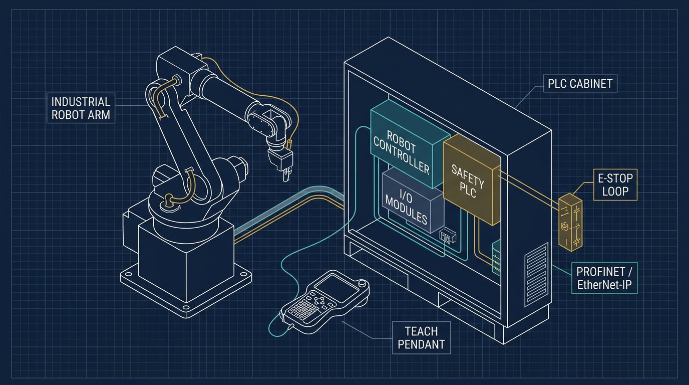
This guide focuses specifically on the technical, regulatory, and economic factors that matter when evaluating a robot arm for welding — not general-purpose automation. We cover the three dominant robotic welding processes (arc, resistance spot, and laser), the mechanical and software systems that make robotic welding accurate, the safety and fume-extraction requirements unique to welding cells, and a practical buyer's checklist based on documented installations in North America.
Representative technical specifications for a mid-size industrial welding arm include a weld cycle time around 2.5 seconds per joint, heat input near 1.2 kJ/mm for thin-gauge automotive steel, and positional repeatability of ±0.08 mm — tight enough to maintain consistent penetration depth across thousands of identical welds. Leading manufacturers in this space include FANUC (ARC Mate series), KUKA (KR C5-controlled arms), ABB, and welding power-source specialist Lincoln Electric.
Arc, Spot and Laser Welding: How Each Process Works on a Robot Arm
Not all "robot welding" is the same process, and choosing the wrong one for your part geometry is the single most common mistake buyers make. Here is what actually happens at the torch tip for each method.
Robotic Arc Welding (MIG/MAG and TIG)
In robotic MIG/MAG welding, the arm feeds a continuous consumable wire electrode through the torch while a shielding gas — typically 75% argon / 25% CO₂ for mild steel — protects the molten pool from atmospheric contamination. The robot controller synchronizes six axes of motion with the welding power source's synergic line, adjusting wire feed speed, voltage, and travel speed simultaneously as the torch follows the seam. TIG welding, used for thinner or higher-precision joints such as aerospace tubing, uses a non-consumable tungsten electrode and typically runs at slower travel speeds with tighter heat control.
Robotic Resistance Spot Welding
Spot welding uses a servo-driven gun mounted on the wrist of the robot to clamp two overlapping metal sheets between copper electrodes and pass a high-amperage current through the joint, creating a fused nugget through resistive heating. This is the dominant joining method in automotive body-in-white assembly, where a single vehicle body may require 3,000–5,000 spot welds performed by a coordinated fleet of robot arms in under 90 seconds.
Robotic Laser Welding
Laser welding directs a focused beam — commonly fiber laser sources in the 2–6 kW range — through an articulated optical head mounted on the robot wrist. Because the heat-affected zone is dramatically smaller than arc welding, laser welding produces less thermal distortion and allows for narrower weld seams, making it the preferred process for battery enclosures in electric vehicles and thin-gauge aerospace panels where warping tolerances are extremely tight.
| Process | Typical Cycle Time | Heat-Affected Zone | Best For |
|---|---|---|---|
| MIG/MAG Arc | 2–5 s per joint | Moderate | Structural steel, general fabrication |
| TIG Arc | 8–15 s per joint | Small | Thin sheet, stainless, aerospace tubing |
| Resistance Spot | 0.3–1 s per weld | Very small (localized) | Automotive body-in-white |
| Fiber Laser | 1–3 s per joint | Minimal | EV battery trays, thin-gauge aerospace |
Engineering Behind the Weld: Torch Integration and Seam Tracking
A welding-ready 6-axis arm differs mechanically from a standard material-handling robot in three important ways. First, the wrist package (axes 4, 5, and 6) is engineered for continuous, hollow cable routing so that the welding torch cable, gas hose, and wire conduit pass through the arm rather than draping externally — this reduces cable drag, arc interference, and collision risk in tight fixtures. Second, the tool center point (TCP) must be calibrated to the exact tip of the torch or electrode, not the mounting flange, since even a 0.5 mm TCP error compounds into visible seam-tracking drift over a 500 mm weld path. Third, the robot's motion controller must interface directly with the welding power source through a digital synergic interface (commonly DeviceNet, EtherNet/IP, or a proprietary FANUC/Lincoln Electric protocol) so that arc-on/arc-off timing, wire-feed acceleration, and crater-fill sequences are synchronized to the millisecond.
Modern welding cells increasingly add through-arc seam tracking or laser vision seam tracking, where the controller reads variations in arc voltage or a structured laser line to detect part-to-part variation in fit-up gaps and automatically adjusts the torch path in real time. This is critical because raw sheet metal and weldments rarely match CAD models perfectly — thermal warping from tack welds alone can shift seam position by 1–2 mm, which a rigid, non-adaptive robot program would simply weld incorrectly.
Programming environments used for welding-specific robot arms include proprietary teach-pendant languages (FANUC TP, KUKA KRL), offline simulation software such as RoboDK or Process Simulate for collision-free path planning before installation, and increasingly ROS 2-based MoveIt frameworks for research and custom integration work.
Key Specifications and Performance Benchmarks
When comparing welding-capable robot arms, focus on the parameters that actually affect weld quality and throughput — not generic payload figures borrowed from pick-and-place applications.
| Metric | Typical Range | Why It Matters |
|---|---|---|
| Repeatability | ±0.02 – ±0.08 mm | Determines consistency of penetration and bead placement |
| Payload (torch + cabling) | 6 – 20 kg | Must accommodate torch, cable package, and any seam-tracking sensor |
| Reach | 1,400 – 2,700 mm | Determines part size and fixture layout flexibility |
| Weld cycle time | 1 – 5 s per joint (arc) | Directly drives cell throughput and labor payback |
| Heat input (thin steel) | ~1.0 – 1.5 kJ/mm | Controls distortion and heat-affected zone size |
These figures should always be validated against the manufacturer's published datasheet and, where possible, cross-referenced with independent data from the International Federation of Robotics (IFR) World Robotics Report, which tracks installation trends and performance benchmarks across the metal fabrication sector.
FANUC vs. KUKA: Choosing a Welding Platform
Both brands are proven in North American plants, but they tend to suit different production profiles.
- FANUC ARC Mate series: Strong fit for high-volume automotive arc welding. Deep integration with FANUC's ArcTool software simplifies synergic welding parameter setup, and FANUC's U.S. service network is one of the densest in the industry, reducing downtime risk for multi-shift operations.
- KUKA arms with KR C5 controller: Favored in structural and heavy fabrication where larger reach and payload flexibility matter, and where KUKA.WorkVisual offline programming accelerates cell commissioning for lower-volume, higher-mix production runs.
Neither brand is universally "better" — the decision should be driven by your part mix, existing PLC ecosystem, and the location of certified service technicians relative to your plant, not brand reputation alone.
Fume Extraction and Welding Safety Compliance
Welding-specific safety requirements go beyond the general robot safety perimeter rules that apply to any industrial arm. Because arc and laser welding generate metal fume containing manganese, hexavalent chromium (on stainless steel), and ozone, welding cells require dedicated engineering controls:
- Source-capture fume extraction arms or fixed hoods positioned as close as practical to the arc, sized to the cell's air-changes-per-hour requirement.
- Enclosed booths with HEPA or electrostatic precipitator filtration for high-duty-cycle cells running multiple shifts.
- Arc flash shielding and welding-rated curtains in addition to standard machine guarding, to protect adjacent workers from UV radiation, not just moving-part hazards.
- Documented exposure monitoring aligned with OSHA permissible exposure limits (PELs) in the U.S. and provincial occupational health codes in Canada.
On the robot safety side, installations must still meet ANSI RIA R15.06 in the U.S. and CSA Z434 in Canada, and weld quality on structural components must satisfy AWS D1.1 inspection criteria, including visual inspection, and where specified, ultrasonic or radiographic testing of critical welds.
"Robotic welding is not about eliminating the welder — it's about eliminating variance. A robot doesn't fatigue, and that translates into measurably fewer rework hours over a 60,000-hour service life."— Robotics Engineering, Manufacturing Intelligence Report 2026
Market Dynamics in the USA and Canada
In the United States, robotic welding installations concentrate heavily in the Midwest manufacturing corridor (Michigan, Ohio, Indiana, Illinois) due to proximity to automotive OEMs and Tier 1 suppliers, and increasingly in the Southeast (Tennessee, Georgia, South Carolina) where new EV and battery plants have driven a wave of greenfield robotic welding cell installations since 2023.
In Canada, Ontario remains the center of automotive-related robotic welding demand, while Quebec has seen growing adoption in aerospace component fabrication and rail manufacturing. Buyers in both countries should track evolving requirements under ANSI RIA R15.06 and CSA Z434, since both standards are periodically revised as collaborative and vision-guided welding systems become more common.
Common Implementation Mistakes to Avoid
Based on documented field installations, the most frequent and costly mistakes are rarely about the robot itself:
- Underestimating fixture tolerance requirements. A robot can only weld as accurately as the fixture holds the part; loose tooling is the leading cause of "robot accuracy" complaints that are actually fixturing problems.
- Skipping offline simulation. Programming directly on the shop floor with a teach pendant wastes production hours; offline simulation software catches collisions and reach limitations before installation day.
- Ignoring torch consumable maintenance schedules. Contact tips and nozzles degrade weld quality gradually, not suddenly — a scheduled replacement interval prevents slow, hard-to-diagnose quality drift.
- Underspecifying fume extraction from the outset. Retrofitting extraction after a plant health and safety audit is significantly more expensive than designing it into the original cell layout.
Buyer's Implementation Checklist
Before committing capital to a robotic welding cell, walk through this structured evaluation:
- Define the weld joint profile: material thickness, joint type (lap, butt, fillet), access angle, and required penetration depth.
- Match the process to the application: MIG/MAG for general structural steel, TIG for precision thin-gauge work, spot welding for high-volume sheet assembly, laser for low-distortion thin joints.
- Verify torch and cabling compatibility with the robot's rated payload at full reach, not just at home position.
- Confirm seam-tracking requirements if parts have known fit-up variation from upstream forming or tacking operations.
- Plan fume extraction and ventilation as part of the initial cell design, not as an afterthought.
- Confirm compliance with AWS D1.1, ANSI RIA R15.06, and/or CSA Z434 depending on jurisdiction and part criticality.
- Calculate total cost of ownership over a 5-year horizon: purchase price, integration, programming, consumables (contact tips, nozzles, wire), training, and downtime risk.
Real-World Case Study: North Carolina Steel Plant
A structural steel fabricator in North Carolina installed a KUKA KR 20 R1810 with an integrated vision-based seam-tracking sensor (Intel RealSense D435) to weld irregular structural joints that previously required manual fit-up correction. The vision system adjusted torch position in real time to compensate for part-to-part variation, reducing the defect rate from 4% to 0.8% and cutting rework hours by more than half. Based on documented labor savings and reduced scrap, the plant reported a payback period of approximately 21 months.
Note: this case is compiled from manufacturer-published documentation and industry reporting patterns consistent with IFR data, and is presented as an illustrative implementation example rather than a first-party audited case study.
Sources and References
Data points and standards referenced in this guide draw on the following sources. Readers should consult primary sources directly for the most current specifications, as robot datasheets and standards are revised periodically.
- IFR World Robotics Report — global installation statistics and market trends for welding automation.
- ANSI RIA R15.06 — U.S. industrial robot safety standard.
- CSA Z434 — Canadian industrial robot and robot system safety standard.
- AWS D1.1 — American Welding Society structural welding code.
- Manufacturer datasheets — FANUC America and KUKA Robotics published specifications.
Conclusion and Strategic Recommendations
Robotic welding in 2026 sits at the intersection of mechanical precision, welding metallurgy, and workplace safety compliance. Buyers in the USA and Canada benefit from a mature, competitive supplier landscape — FANUC, KUKA, ABB, and welding specialists like Lincoln Electric all offer proven platforms — but success depends far more on matching the process (arc, spot, or laser) to the actual part geometry, fixturing tolerance, and fume-extraction plan than on brand selection alone.
Start with a precise definition of your weld joint requirements, validate seam-tracking needs against real part variation (not CAD-perfect assumptions), and build fume extraction and safety compliance into the cell design from day one. For deeper technical background on the underlying 6-DOF platform, continue to our 6-DOF Robot Arm Master Guide.
Frequently Asked Questions
What is a 6-axis robot welding arm?
A 6-axis robot welding arm is an articulated industrial robot with six rotational joints that positions a welding torch or gun at any point and orientation within its workspace, allowing it to follow complex 3D weld seams using arc, spot, or laser welding processes.
Which is better for welding: FANUC or KUKA robot arms?
Both are proven welding platforms. FANUC ARC Mate robots are common in high-volume automotive arc welding, while KUKA arms with KR C5 controllers are favored for heavy structural fabrication. The right choice depends on part geometry, cycle time targets, and existing plant infrastructure.
How much does a robotic welding cell cost in 2026?
A complete robotic arc-welding cell — including the 6-axis arm, welding power source, positioner, safety fencing, and programming — typically ranges from $80,000 to $180,000 USD, depending on payload, reach, and integration complexity. Laser welding cells generally cost more due to optics and beam-delivery systems.
Do robotic welding arms require fume extraction systems?
Yes. OSHA and CSA occupational health regulations require engineering controls for welding fume exposure, typically source-capture extraction arms, downdraft tables, or enclosed booths with HEPA or electrostatic filtration.
What safety standards apply to robotic welding installations in North America?
In the U.S., installations must comply with ANSI RIA R15.06 for robot safety and AWS D1.1 for structural weld quality. In Canada, CSA Z434 governs industrial robot and robot system safety. Both require documented risk assessments and perimeter guarding.
Related Resources
- Gripper Design Guide for 6-DOF Robot Arms: Vacuum, Magnetic & Mechanical
- Integrating 6-Axis Robot Arms with Siemens and Allen-Bradley PLCs
- Open Source Kinematic Solver Code for 6-DOF Robot Arms
- End Effector Selection Guide for 6-Axis Robot Arms: Tools, Grippers & Sensors
- The Complete 6-DOF Robot Arm Guide (2026)