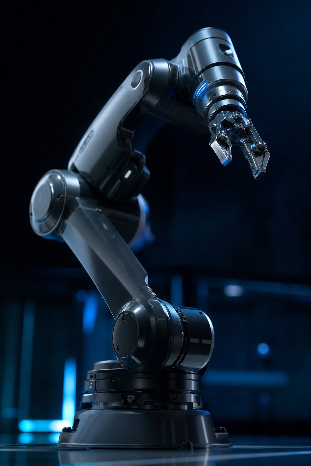
Safety boundary: This article explains the engineering decisions behind a robot base support. It does not size a structural foundation or approve an anchor installation. The robot manufacturer’s installation manual, a qualified mechanical/structural engineer, the site risk assessment, and local building requirements govern the final design.
Start with the robot manual, not the anchor catalogue
Robot arm base mounting is often treated as a drilling task: copy the bolt pattern, drill a few holes, tighten the nuts, and power up. That sequence ignores the load path. A robot base must transfer the arm’s weight, acceleration forces, emergency-stop reactions, tool loads, and overturning moment into a support that remains stiff and stable. If the support flexes or shifts, the controller may still report the same joint positions while the tool moves differently in space.
The first document to obtain is the current product manual for the exact robot model, payload variant, mounting orientation, and controller. Manufacturer drawings specify bolt-hole diameter and pattern, base dimensions, allowable orientations, tightening torque, locating pins, foundation flatness, reaction loads, and sometimes a minimum concrete grade or reinforcement arrangement. A generic M-size bolt recommendation is not a substitute for those values.
Universal Robots, for example, lists different base interfaces for different models: its published table shows M8 bolts at 20 N·m for several smaller arms and six M10 bolts at 45 N·m for the UR20. Those values belong to those interfaces and should not be copied to a FANUC, ABB, KUKA, or custom arm. The UR20 user manual also warns that unstable mounting can result in injury. The lesson is simple: identify the interface first, then design the support around the specified load and fastener system.
What the base must resist
Four load categories should be considered together. The static vertical load includes the robot mass, pedestal, tooling, workpiece, and any mounted cable carrier. The overturning moment comes from the centre of mass being offset from the support plane. Horizontal shear comes from acceleration, deceleration, process forces, and emergency stops. Vibration and cyclic loading can loosen or fatigue a connection even when a one-time static calculation looks acceptable.
Manufacturers may publish forces and moments in a coordinate system attached to the base. Copy those directions carefully. A force marked Fz may be vertical for one mounting orientation and horizontal for another. A moment is not the same as payload torque at the wrist. The base load table is the source for the foundation and anchors; the payload diagram is the source for the tool and workpiece limits.
Illustrative scenario — not a Robotics Engineering Lab test: Imagine a 250 kg arm mounted on a steel pedestal. A simplified design check uses a 2.45 kN weight and a hypothetical 6 kN·m overturning moment from the manufacturer’s load table. If four anchors share the tension evenly, the simple lever estimate is not enough to determine the most highly loaded anchor because the bolt spacing, base-plate stiffness, concrete edge distance, grout contact, and load direction all matter. The correct conclusion is to send the manufacturer’s reactions and the support geometry to a qualified engineer, not to declare that each anchor carries 1.5 kN.
For a small desktop arm, the same principles appear at a different scale. A thin acrylic base can be adequate for slow educational motion but twist under fast reversal. A 6 mm plate may be rigid enough for one arm and too flexible for another. Repeatability claims are meaningful only when the mounting surface, fasteners, tool, payload, and calibration state match the conditions under which the claim was specified.
Choose the support architecture
Direct floor mounting
Direct mounting is appropriate when the concrete slab, embedded steel, and cell layout can carry the specified reactions. It minimizes the number of interfaces and usually gives the best stiffness-to-height ratio. The installer still needs to locate reinforcement, utilities, joints, cracks, edge distances, and slab thickness before drilling. A “concrete floor” is not automatically a suitable structural foundation.
Steel base plate or adapter plate
An adapter plate translates the robot’s bolt pattern to an existing floor or pedestal. Its thickness and ribbing must resist bending between robot and anchors. The plate should have a defined datum, machined or controlled contact surface, compatible hole tolerances, and a corrosion treatment suited to the environment. Slotting holes can make alignment easier, but slots change load transfer and should not be used casually in a high-cycle cell.
Pedestal, riser, or mobile platform
A riser can place the robot in a better work envelope or move the inner-workspace singularity away from the task. It also raises the centre of mass and increases overturning demand. A mobile platform adds casters, leveling feet, welds, bolted joints, and possible floor irregularity. The platform must be secured in its production position and, when required, interlocked so the robot cannot operate while the base is not locked.
For a collaborative arm or a small educational arm, a commercially designed base may be useful because its interface and locating method are documented. An indicative 2026 example is the ROBOTIS Base Plate-01, listed at US$688.62 on the manufacturer’s US site. That price is a reference for a specific small-manipulator accessory, not a universal industrial base price. Industrial risers and large welded skids can cost thousands of dollars before installation and engineering.
Flatness, level, stiffness, and repeatable location
Level and flatness are related but not identical. Level describes orientation relative to gravity. Flatness describes how much the mounting surface departs from a plane. A robot controller can often compensate for a permitted mounting angle, but it cannot make a flexible or rocking base rigid. A surface can be level yet locally warped under one foot, or flat enough for a plate but not stiff enough for the robot’s reaction moment.
Manufacturer requirements vary. An ABB product manual example specifies foundation flatness of 0.1 mm over 500 mm for the referenced robot model and notes that a flat foundation helps preserve resolver calibration. Kawasaki’s CX Series installation manual gives its own installation dimensions, high-tension bolt requirements, levelness information, and a steel-plate/concrete arrangement. These values are examples from specific manuals, not a generic tolerance for all arms.
Use a calibrated straightedge, feeler gauges, precision level, or survey method appropriate to the required tolerance. Do not pull a warped plate flat by over-tightening one corner; that can preload the robot base and distort the structure. Where the manufacturer permits shims or liners, use a defined material and thickness, support the full load path, and document the final condition. Non-shrink grout may be appropriate under a designed base, but its use, gap, cure time, and installation process must be specified rather than improvised.
For repeatable relocation, separate the functions of load transfer and location. High-strength bolts clamp the interface; dowel or positioning pins can establish the repeatable shear datum. Universal Robots recommends positioning-pin features for accurate re-mounting on several interfaces. Pins are not a reason to reduce the required bolt preload, and they must be sized and toleranced for the actual plate and robot holes.
Anchor selection: expansion, screw, or cast-in
Anchor selection depends on concrete strength, cracked or uncracked condition, edge distance, embedment, seismic demand, corrosion, installation access, and the design tension and shear. An expansion wedge anchor is not automatically interchangeable with a screw anchor or a cast-in bolt. Follow the anchor manufacturer’s evaluation report and installation instructions, including drill diameter, hole cleaning, embedment, minimum spacing, torque, and inspection.
Indicative 2026 hardware reference: a Home Depot listing showed a Hilti 3/4 in × 10 in Kwik Bolt TZ2 carbon-steel wedge-anchor ten-pack at US$235.48 when checked for this article. The same listing showed a Simpson Strong-Tie 3/4 in × 10 in Strong-Bolt at US$11.68 for a single anchor. These are retail reference prices, not a design recommendation, and prices, availability, tax, and delivery change. Anchor capacity cannot be inferred from price or diameter alone.
For a retrofit, a qualified engineer may choose a post-installed anchor system after checking the concrete and the manufacturer’s published capacities. For a new foundation, cast-in anchors or embedded plates can provide a predictable load path, but their location tolerance and template need to be controlled during concrete work. If the robot will be installed near a slab edge, joint, opening, or existing reinforcement, stop and obtain a structural review before drilling.
- Use a scanner or construction records to locate reinforcing steel, conduits, and post-tensioning before drilling.
- Record the concrete condition and strength assumptions; do not treat an unknown slab as rated concrete.
- Keep the anchor type, embedment, spacing, and edge distance consistent with the evaluation data.
- Clean drilled holes using the anchor manufacturer’s stated sequence. Dust left in a hole can reduce installation quality.
- Use a calibrated torque tool and record the final torque, but do not use torque as a substitute for the full capacity check.
Installation workflow from drawing to dry run
- Freeze the configuration. Record robot model, mounting orientation, payload, tool, workpiece, cable route, and the maximum operating speed before designing the base.
- Review the load data. Obtain base reactions, bolt data, foundation requirements, and lifting instructions from the current manual. Ask the manufacturer when the data does not cover the custom orientation.
- Survey the site. Confirm slab thickness, reinforcement, utilities, edge distances, access, drainage, vibration sources, and the full robot/tool/workpiece envelope.
- Fabricate and inspect the support. Check plate thickness, hole pattern, weld quality, machined datums, corrosion protection, and access for the specified wrench and cable connectors.
- Install the anchors and plate. Follow the selected anchor system’s drilling, cleaning, setting, torque, and cure procedure. Keep the robot supported and out of the drop zone while it is unsecured.
- Level without distortion. Use the permitted shims or grout method, tighten in the stated pattern, and recheck flatness after preload is applied.
- Configure the controller. Set mounting orientation, gravity, tool load, centre of gravity, frames, and any calibration data required by the manufacturer.
- Commission at restricted speed. Test emergency stop, protective stop, limits, cables, clearances, and the entire reachable envelope before enabling production speed.
Lockout/tagout applies during drilling, anchoring, wiring, lifting, and mechanical adjustment. A robot can move when a program restarts, when power is restored, or when a stored joint position is called. The integrator must identify stored energy, gravity-driven motion, pinch points, suspended loads, and the response of the complete cell. ANSI/RIA R15.06, CSA Z434, ISO 10218, and local workplace requirements may apply depending on the installation and jurisdiction.
Commissioning checks that catch loose bases
Before the first automatic cycle, inspect each fastener, dowel, shim, weld, anchor, leveling foot, and cable strain relief. Mark fasteners only after the specified tightening method is complete, so a witness mark can help identify later movement. Verify that the robot does not contact its pedestal, cable, guard, fixture, or nearby machine at all programmed poses.
Run a low-speed repeatability check at several orientations, including positions that produce high base reactions. If the TCP moves after a direction reversal, compare the result with the joint and base frame data. A shifting base, loose tool, bad mastering, elastic deflection, or collision can produce similar symptoms. The site’s robot arm calibration guide explains why absolute accuracy and repeatability should not be confused.
After an initial thermal and operating period, recheck accessible fasteners and the support for settling, grout damage, fretting, paint witness movement, or cracks. The interval should follow the manufacturer and site maintenance plan rather than a universal “retorque after one week” rule. Add the support to the robot arm maintenance schedule, and include base movement as a specific inspection item.
Common base-mounting mistakes
- Copying bolt torque from another robot. Torque is determined by the fastener, interface, lubrication, grade, clamp requirement, and manufacturer design.
- Mounting to a thin sheet or unbraced table. The robot may appear stable at low speed and deflect at production acceleration.
- Ignoring the riser’s centre of mass. A taller stand changes overturning demand and can introduce a rocking mode.
- Drilling through a slab joint or reinforcement. The hole may be physically possible and structurally unsuitable.
- Using slots without a shear datum. A slotted plate can allow creep unless the designed clamp and locating features carry the load.
- Assuming controller compensation fixes a flexible base. Calibration can correct measured geometry; it cannot guarantee a structure that changes under load.
For the complete cell context, use the site’s robot safety standards guide and the master guide linked from the article footer. A base is a mechanical safety component as well as a precision component: if it can tip, slide, or detach, the cell is not ready for production.
Sources and methodology
Technical requirements in this article are deliberately model-specific. Universal Robots sources provide documented base bolt sizes, torques, and locating-pin guidance for named models. ABB and Kawasaki installation manuals demonstrate how different manufacturers state flatness, foundation, bolt, and installation requirements. Retail prices are included only as reference examples checked August 21, 2026; they are not Robotics Engineering Lab inventory or a quotation.
- Universal Robots: Mounting & Installation — base interfaces and recommended torques; accessed August 21, 2026.
- Universal Robots UR20 mounting description — six M10 bolts, 45 N·m, and secure mounting warning; accessed August 21, 2026.
- ABB IRB 14000 product manual — installation personnel, foundation flatness, and calibration context; accessed August 21, 2026.
- Kawasaki CX Series installation and connection manual — foundation, high-tension bolts, steel plate, and installation workflow; accessed August 21, 2026.
- Home Depot Hilti anchor listing — indicative retail reference price; accessed August 21, 2026.
- ROBOTIS Base Plate-01 — manufacturer listing and indicative accessory price; accessed August 21, 2026.
Frequently asked questions
Why must a robot arm base be anchored?
Anchoring transfers the robot’s weight, acceleration, emergency-stop reactions, and overturning moment into a designed support. It also prevents sliding or tipping when the robot changes direction. The required anchor type, size, spacing, and torque must come from the robot and anchor manufacturers and the foundation design.
Can I bolt a robot arm directly to a concrete floor?
You can only do so when the floor, concrete condition, reinforcement, edge distance, anchors, and robot reaction loads meet the manufacturer’s and engineer’s requirements. A generic concrete slab may be too thin, cracked, close to a joint, or unable to carry the specified moment.
How flat should a robot arm mounting surface be?
The exact flatness is model-specific. For example, an ABB product manual cited in this guide gives a flatness value of 0.1 mm over 500 mm for its referenced robot. Do not apply that number to another arm; use the current product manual and measure after the final preload is applied.
Should I use chemical anchors or wedge anchors for a robot base?
Neither is automatically correct. The choice depends on concrete condition, cracked or uncracked design, embedment, spacing, edge distance, seismic demand, corrosion, installation access, and the anchor’s published evaluation data. A qualified engineer should select and approve the system.
Do I need dowel pins on a robot arm base?
Dowel or positioning pins can establish a repeatable shear datum when the manufacturer provides pin holes and tolerances. They do not replace the specified bolts or clamp preload. Use the robot manual’s pin size, material, fit, and installation method rather than adding arbitrary pins.
What should I check before the first robot motion?
Verify fastener torque records, anchor installation, flatness, level, support stiffness, mounting orientation, tool load, cable routing, work envelope, guarding, emergency stop, protective stops, and the complete risk assessment. Run the first motion at restricted speed with qualified personnel outside the hazard zone.