Editorial Disclosure & Technical Scope
This article is a reproducible worked-example tutorial: every formula and number below can be checked against the cited datasheets and documentation. Robotics Engineering Lab has not operated the specific hardware combinations described; the current-budget, inrush, wire-gauge, and brownout behavior follow from published servo and controller specifications plus well-established DC circuit physics. Follow local electrical codes, use a qualified electrician for mains-connected work, and never modify live equipment.
Why Robot Arms Brown Out: Voltage Drop Physics
Power supply sizing for a robot arm is the process of matching a DC supply's voltage, continuous current rating, and transient energy to the actuators' real load profile — and the reason so many builds fail is that the load profile is far more demanding than the datasheet's "running current" suggests. Most "the arm twitches, the controller resets" problems are not controller bugs; they are voltage physics. A DC rail carrying current I through wiring of total round-trip resistance R loses V = I × R volts. When several servo or stepper joints accelerate at once, the current spikes, the rail sags, and the microcontroller's brownout detector trips even though the power supply nameplate looks generous.
Consider a controller with a 3.3 V logic rail. Its brownout detector resets the chip when the rail sags below the detection threshold (roughly 2.4–3.0 V depending on ESP32 model and configuration, per Espressif documentation). A 0.5 V sag on a 3.3 V rail is enough to reset the controller, and a 0.5 V sag is easy to produce: 15 A through 33 milliohm of wiring, or 10 A through 50 milliohm. Thin jumper wires, breadboard rails, and USB cables routinely measure 50–200 milliohm, which is why builds that worked on a bench fail the moment all six joints move.
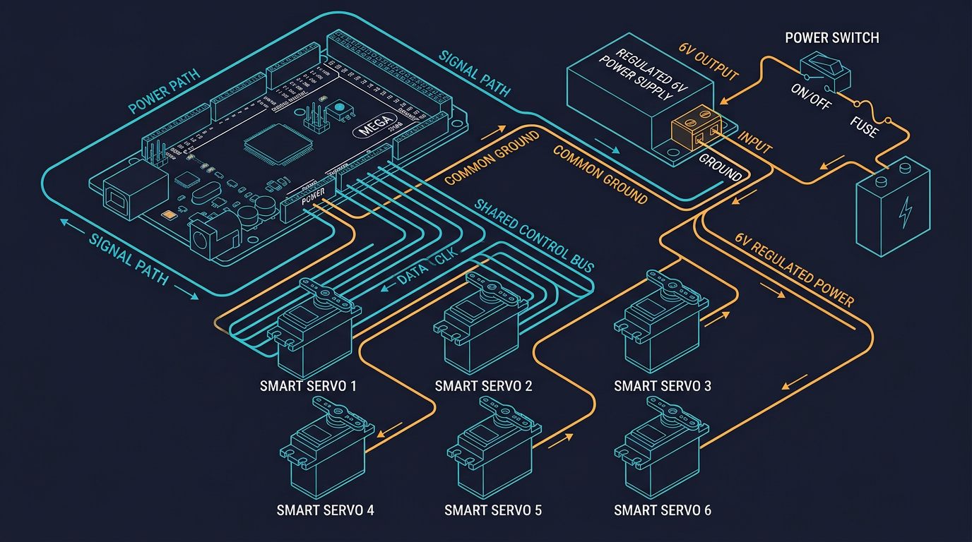
The fix is architectural, not a bigger fuse: a separate actuator supply, short thick power wiring, a bulk capacitor bank at the load, and a single-point ground. The five steps below build that architecture and then verify it with measurements.
Step 1 — Build the Current Budget
The current budget starts from datasheet numbers, not from the average "running current" listed on a product page. For a typical hobby servo such as the MG996R, the published figures are roughly 500–900 mA running at 6 V and a stall current near 2.5 A at 6 V; many 20 kg·cm class digital servos are similar. For a six-axis arm, the worst case is that several joints command full torque simultaneously, so the budget must sum worst-case stall currents, not running currents.
Example calculation: six hobby servos
Assumptions: six joints, each with 2.5 A stall at 6 V and 0.8 A typical running current; worst case assumes the five base joints plus the wrist can command stall simultaneously during a fast move.
Worst-case budget: 6 × 2.5 A = 15 A at 6 V.
Continuous budget with duty cycle: a 3 s cycle with 1.5 s of motion at 2 A per servo and 1.5 s of holding at 0.5 A gives RMS current per servo of sqrt((2² × 1.5 + 0.5² × 1.5) / 3) ≈ 1.46 A; six servos ≈ 8.8 A RMS, 90 W at 6 V.
Margin rule used by integrators: multiply the worst-case stall sum by 1.5–1.6 to cover inrush and supply aging: 15 A × 1.6 ≈ 24 A. A supply rated 20 A continuous with short-term 30 A peak, or 25 A continuous, is the realistic purchase target for this arm.
For a stepper-driven arm such as an AR4-class 24 V build, the same method applies with the motor/driver currents: six NEMA-23-class steppers with 3–4 A per-axis driver current sum to roughly 18–24 A worst case at 24 V if every axis commanded full current at once, though drivers rarely do. The platform's published bill of materials specifies the power-brick class to order, and the same 1.5× margin rule applies to the summed driver ratings. Industrial servo drives are budgeted differently — see Step 6.
Step 2 — Choose the Voltage Rail
The rail voltage is set by the actuators and the controller, not by convenience. Common rails for robot arms:
| Rail | Typical loads | Notes |
|---|---|---|
| 5.0 V | Analog hobby servos (4.8–6.6 V class), PCA9685 V+ | Voltage drop is critical: a 0.5 V sag drops torque noticeably |
| 6.0–7.4 V | Digital bus servos (Dynamixel, Feetech, Hiwonder classes) | Higher voltage raises speed and stall torque; check the servo's max rating |
| 12 V | Small linear actuators, some grippers, 12 V stepper systems | Common accessory rail; often derived from the main rail |
| 24 V | AR4-class stepper arms, most light industrial DC servo drives, UFACTORY xArm control boxes | 24 V DC is the de facto industrial low-voltage rail |
| 48 V+ / 230 V AC | Higher-power servo drives and AC servos | Requires qualified electrical work, proper fusing, and enclosure |
| 3.3 / 5 V logic | Arduino, ESP32, drivers' logic side | Always derived from a separate regulator or supply, never from the actuator rail |
Two rules follow from the table. First, keep the logic rail separate from the actuator rail: the controller runs from its own regulator or a small DC-DC module, and only signal plus ground cross to the servo side. Second, never run the actuator rail through the microcontroller's 5 V pin; the Arduino Mega's onboard regulator is rated around 1 A total and an ESP32's 3.3 V regulator less. The ESP32 controller guide and the Arduino Mega wiring guide both show the logic/servo separation in practice.
Step 3 — Power Supply Sizing: Continuous Rating, Inrush, and Capacitance
With the current budget in hand, the supply selection has three parts: continuous rating, peak/inrush behavior, and bulk capacitance.
Continuous Rating and Peak Headroom
The supply must deliver the RMS budget continuously (8.8 A in the example above) and the worst-case peak for long enough that the motion completes (24 A target). Switching supplies handle peaks poorly when run at their limit: many fold back current, which looks exactly like a brownout. Buying a supply rated 1.5–1.6× the worst-case sum, as in Step 1, keeps the supply out of foldback during normal motion.
Inrush and the Bulk Capacitor Bank
No supply responds instantly. When servos start, they demand current for tens of milliseconds before the supply's feedback loop catches up. The bulk capacitor bank supplies that transient. The sizing formula is:
C = I × dt / dV
where I is the transient current (A), dt the transient duration (s), and dV the sag you allow (V).
Example calculation: capacitor bank
Assumptions: 15 A inrush for 20 ms (typical for several servos starting together) with an allowed sag of 0.5 V at the servo terminals.
C = 15 × 0.020 / 0.5 = 0.6 F (600,000 µF).
This is why a single 470 µF or 1,000 µF capacitor is nowhere near enough for a multi-servo arm, and why builders use banks of large low-ESR electrolytic capacitors or a battery (which is itself a huge capacitor bank). If the wiring is shortened so the sag allowance rises to 1.0 V and the inrush window is 10 ms, the requirement falls to 0.15 F — still large, but achievable with a modest bank. Always measure, rather than assume, the actual inrush duration.
Linear supplies sag less on fast transients than cheap switching supplies but waste more heat; regulated switching supplies with active current sharing are the usual choice for hobby arms, and for industrial servo systems the equivalent is the drive's regulated DC bus with its own built-in capacitance, as explained in Step 6.
Step 4 — Wire, Fuse, and Ground the Supply
Wiring converts a correctly sized supply into an incorrectly behaving one faster than any other mistake. Size the wire so the round-trip drop stays under about 0.3 V at worst-case current.
Example calculation: wire gauge for 15 A
Budget: 0.3 V ÷ 15 A = 0.02 Ω total round-trip. For a 2 m round trip (1 m out, 1 m return), that is 0.01 Ω/m ≈ 10 mΩ/m.
- 14 AWG (copper, ≈8.3 mΩ/m): drop = 15 × 0.0083 × 2 ≈ 0.25 V ✓ passes
- 16 AWG (≈13.2 mΩ/m): drop = 15 × 0.0132 × 2 ≈ 0.40 V ✗ fails the 0.3 V budget
- 18 AWG (≈20.9 mΩ/m): drop ≈ 0.63 V ✗ unacceptable
Rule: use the same gauge for the return path, keep the wire short, and put the capacitor bank at the load end, not at the supply.
| AWG (copper) | Resistance (mΩ/m, 20 °C) | Max current for ≤0.3 V drop over 2 m round trip |
|---|---|---|
| 22 | ≈53 | ≈2.8 A |
| 20 | ≈33 | ≈4.5 A |
| 18 | ≈21 | ≈7 A |
| 16 | ≈13 | ≈11 A |
| 14 | ≈8.3 | ≈18 A |
| 12 | ≈5.2 | ≈29 A |
Fusing: place a slow-blow fuse (or resettable fuse) in each positive branch near the supply, rated about 1.25× the branch's continuous maximum, so it clears faults without tripping on motor inrush. Grounding: use a single-point (star) ground where the logic ground and the servo ground meet exactly once; long ground paths shared between logic and motors turn servo current into logic noise and are a classic source of random resets. If the controller and servos must be far apart, run a dedicated ground return for the servo rail and keep the signal ground separate until the star point.
Step 5 — Commission with Checkpoints
Commissioning is where the numbers become measurements. Run these checkpoints in order, and do not skip to the next one until the current one passes.
- No-load voltage check: with the arm powered but idle, measure the rail at the servo terminals (not at the supply). It must hold within 2% of nominal.
- Single-joint test: command one joint through its fastest move and watch the terminal voltage with a scope or fast multimeter. Sag must stay under 0.3 V. If it sags more, the wire or the capacitor bank is undersized before you ever get to multiple joints.
- Worst-case synchronized test: run the motion that commands the most joints at once (typically a full-extension diagonal move). Record the minimum voltage and the duration of the sag. This is the test that reproduces "random" resets.
- Controller brownout test: with an ESP32 or Arduino logging to serial, repeat the worst-case move and confirm no brownout/reset messages. For ESP32, the message is the well-known "Brownout detector was triggered" line; if it appears, the logic rail is sagging and needs its own regulator/buffer rather than a bigger servo supply.
- Thermal test: run the production duty cycle for 30 minutes. The supply case and capacitor bank should stay below roughly 70 °C; a hot supply is a derating and reliability problem, not just a comfort problem.
- Ground-noise check: measure AC mV between logic ground and servo ground at the star point; steady readings above ~50 mV warrant a wiring review.
Document the pass/fail values for each checkpoint. That record is what turns a one-off build into a repeatable design, and it is exactly the kind of evidence a reviewer will ask for if the cell is ever expanded. The same checkpoint discipline is described for the full electrical system in the robot cell electrical design.
Step 6 — Industrial Servo Drives: The DC Bus Is Not a Power Supply
Industrial servo drives change the sizing logic. A drive's DC bus is fed by a power supply or a shared-bus module, but the current on the bus is not the sum of motor currents. As Elmo Motion Control's application note explains, motor current at the drive is largely reactive; the supply is sized by the power the drives actually consume, and one supply can feed several drives because peak power from the drives is rarely simultaneous. A supply rated 20 A continuous at a given AC input can feed five or six drives whose nameplates would suggest far more. The equivalent of the hobby-arm capacitor bank is the drive's built-in bus capacitance and the regenerative (shunt) resistor that absorbs deceleration energy. For EtherCAT or other fieldbus-based multi-axis arms, the bus architecture and braking energy handling are covered in the EtherCAT robot arm guide.
The lesson transfers back to hobby arms: measure actual consumption, and size the supply for the power profile, not the arithmetic sum of nameplates. The Step-1 worst-case sum is a starting point, never a substitute for the Step-5 measurements.
Indicative 2026 Prices for Power Hardware
| Component | Representative class | Indicative 2026 price (USD) | Indicative 2026 price (CAD) | Pricing basis |
|---|---|---|---|---|
| 5 V / 20 A switching supply | Generic regulated 100–120 W, Mean Well or equivalent class | $20 – $45 | $27 – $61 | Typical US reseller list |
| 24 V / 15 A supply | Mean Well LRS/S-350-24 class | $40 – $60 | $54 – $81 | Typical distributor list |
| 48 V / 10 A supply | Mean Well RSP-500-48 class | $120 – $170 | $162 – $230 | Typical distributor list |
| Bulk capacitor bank | 100,000–600,000 µF, low-ESR electrolytic, 25–35 V | $30 – $80 | $41 – $108 | Typical US reseller list |
| DC-DC logic rail module | 5 V or 3.3 V, 2–3 A | $8 – $20 | $11 – $27 | Typical US reseller list |
| 14 AWG silicone power wire | Per meter, 2-conductor | $1 – $3 | $1.4 – $4 | Typical US reseller list |
| Fuse holders and fuses | Blade or cartridge, 20–30 A | $8 – $20 | $11 – $27 | Typical US reseller list |
Prices are indicative 2026 reference ranges compiled from typical US and Canadian distributor and reseller listings at the date of writing; exact pricing varies by brand, stock, and region and should be confirmed at purchase. Industrial power supplies and drives are configuration- and quote-dependent.
Typical Reader Question: Why Does My Arm Work on USB but Die on the Supply?
Typical Reader Question
"My six-servo arm runs fine when I power the controller over USB, but as soon as I use my 'big' 10 A power supply, the ESP32 resets during motion. The supply is bigger, so how can it be worse?"
Engineering analysis: The supply is not necessarily the problem; the path is. On USB, the servos are usually running from a different, smaller test supply or from the USB hub's own limit, so the current path is short. With the "big" supply, the wiring is often long and thin (or daisy-chained through the PCA9685's V+ terminals), so the rail at the servos sags under load even though the supply output is fine. Measure at the servo terminals during the failing move: if the supply output stays at 6.0 V but the terminals see 5.2 V, the answer is wire gauge and capacitor placement, not supply current. Also check that the logic rail is fed separately: a shared 5 V rail that sags under servo load will trip the ESP32 brownout detector even with a huge supply behind it.
Safety: Mains Work, Fusing, and Lockout/Tagout
Safety Warning
Work on the AC mains side of any power supply — wiring a plug, an inlet, a disconnect, or a breaker — must be done by a qualified electrician and comply with the applicable electrical code (NEC in the USA, provincial codes in Canada). Always disconnect and lock out the AC supply before working on the DC side of a powered system, verify zero energy with a meter, and never probe live terminals. A robot arm under power can move unexpectedly when a brownout clears; keep hands clear of the arm during testing and use the controller's enable/estop first. This article is educational and does not approve an electrical installation.
Sources and Methodology
- Adafruit Learning System: PCA9685 16-channel PWM/Servo Driver guide (learn.adafruit.com/16-channel-pwm-servo-driver), covering separate V+ servo power and common-ground wiring. Accessed 2026-08-31.
- Espressif documentation: ESP32 brownout detector and power management documentation (docs.espressif.com), including detection thresholds and reset behavior. Accessed 2026-08-31.
- Elmo Motion Control: "Power Supply for Servo Applications" application note (elmomc.com), covering DC-bus sizing, shared supplies, and inrush for servo drives. Accessed 2026-08-31.
- Servo datasheets: MG996R published operating (0.5–0.9 A) and stall (2.5 A @ 6 V) figures, corroborated by the Arduino Forum thread "How do I configure power supply for robot arm?" (forum.arduino.cc, 2022) and Robotics Stack Exchange "Powering 3 MG996R servos" (2023). Accessed 2026-08-31.
- Integrator rule-of-thumb reference: Kpower "Servo Robotic Arm Selection Guide" (kpower.com, 2026) for stall-current and supply-margin guidance (e.g., six 40 kg·cm servos can exceed 36 A peak, recommending a 50 A-class supply with bulk capacitance). Accessed 2026-08-31.
- Platform documentation: Annin Robotics AR4 build manual (anninrobotics.com) for 24 V stepper power expectations. Accessed 2026-08-31.
- Methodology: All formulas are standard DC circuit relations (Ohm's law, RMS, capacitor energy); worked examples state their assumptions and should be re-verified by measurement during commissioning. Prices are indicative 2026 reference ranges from typical distributor listings; no hardware described here was bench-tested by this site.
Frequently Asked Questions
How do I calculate the power supply current for a robot arm?
Sum the worst-case stall current of every actuator that can run at the same time, because a multi-axis arm can command several joints simultaneously. For six hobby servos with a 2.5 A stall current each, that is 15 A worst case; add a 1.5 to 1.6 times margin for inrush and supply aging, which puts you near a 20 to 25 A supply at the servo voltage. For continuous operation, also compute the RMS current from the duty cycle, because the supply must hold the RMS value indefinitely without overheating.
Why does my ESP32 or Arduino reset when the servos move?
The usual cause is voltage sag: when servos start, their stall or inrush current flows through the power wires, and the resistance of thin wires drops the rail below the controller's brownout threshold. The ESP32 brownout detector resets the chip when the supply sags, and the Arduino's onboard regulator does the same on a weaker margin. Fix it with a separate servo power rail (never the controller's 5 V pin), thick short power wires, a bulk capacitor bank near the servos, and a common ground between the logic and power sides.
Can I power servos from the Arduino or ESP32 5 V pin?
No, not for a robot arm. The Arduino Mega 5 V pin is fed through an onboard regulator rated around 1 A total, and the ESP32's 3.3 V regulator is even weaker; a single hobby servo can draw several amps at stall. Servos and motors must run from a separate power supply rated for the actuator current, with only signal and ground connections to the controller. A common ground between the controller and the servo supply is required so the PWM signals have a reference.
Do I need a bulk capacitor bank on a robot arm power supply?
For servo-driven hobby arms, yes, a bulk capacitor bank is the standard fix for transient inrush. The required capacitance is C = I x dt / dV, where I is the inrush current, dt is the duration of the transient, and dV is the sag you allow. A worked example: 15 A inrush for 20 ms with an allowed 0.5 V sag gives C = 15 x 0.02 / 0.5 = 0.6 F, which explains why 470 microfarad caps alone are inadequate and why builders use large electrolytic banks or a battery. Industrial servo drives handle this with a regulated DC bus and built-in capacitance on the drive.
What wire gauge do I need for servo power wiring?
Size the wire so the round-trip voltage drop stays below about 0.3 V at the worst-case current. For 15 A over a 2 m round trip, the resistance budget is 0.3 / 15 = 0.02 ohm, or about 10 milliohm per meter, which requires 14 AWG (8.3 milliohm/m) or larger; 16 AWG (13.2 milliohm/m) gives 0.40 V drop and is too small. Use the same gauge for the return path, keep servo and logic grounds separate until a single star point, and fuse each branch near the supply.
Can one power supply run an entire robot cell including a 24 V stepper arm?
It can, but only with separate fused branches per load group and a budget that sums the worst-case currents of every branch. A 24 V stepper-based arm such as an AR4-class robot needs roughly 6 to 10 A at 24 V when several axes accelerate, plus whatever the gripper and controller draw, while a 5 or 6 V hobby-servo rail is a completely different voltage that needs a DC-DC converter. Most builders use one main supply per voltage rail, fuse each branch, and keep the logic supply separate from the actuator supply to protect the controller.