Editorial Disclosure & Scope Notice
This technical commissioning guide is an educational engineering resource. Values, register maps, and timing budgets presented below derive from published EtherCAT Technology Group (ETG) standards, CiA 402 drive profile specifications, and manufacturer datasheets (Beckhoff, Leadshine, Inovance, Copley Controls). Robotics Engineering Lab did not build a turnkey production cell for this specific article. Commissioning high-power servo drives on industrial manipulators presents serious mechanical pinch, crushing, and electrical shock hazards. Always follow lockout/tagout procedures, verify safe torque off (STO) functionality, and work under the supervision of a licensed controls engineer or qualified system integrator.
The Multi-Axis Motion Bottleneck in 6-DOF Robot Arms
When designing or retrofitting a six-degree-of-freedom (6-DOF) articulated manipulator, coordinating six servo drives with microsecond-level synchronization is the single most critical electrical control challenge. In an articulated arm, the kinematic position of the Tool Center Point (TCP) is a highly non-linear function of all six joint angles. If one joint drive receives its position setpoint even 200 microseconds later than the other five joints, the physical trajectory of the end effector deviates from the planned Cartesian path. This introduces velocity ripple, path tracking errors, and high-frequency structural vibration that degrades surface finish in dispensing, welding, and high-speed pick-and-place operations.
Traditional hobbyist and educational robotic platforms frequently rely on asynchronous serial protocols (such as UART, USB-to-serial converters, or I2C) or multi-drop RS-485 busses. While adequate for desktop educational arms operating under 50 Hz update rates, these interfaces fail completely in dynamic multi-axis industrial motion. Even standard CANopen (operating over ISO 11898 CAN 2.0B at 1 Mbit/s) hits a hard throughput limit: updating cyclic Process Data Objects (PDOs) for six servo drives consumes 5 to 10 milliseconds of bus time, making a true 1 kHz (1,000 Hz) closed-loop trajectory update impossible.
EtherCAT (Ethernet for Control Automation Technology) solves this multi-axis bottleneck by transforming standard 100BASE-TX Fast Ethernet into a deterministic, ultra-low-latency fieldbus. Rather than transmitting discrete addressed packets to each drive sequentially, the EtherCAT master transmits a single Ethernet frame that passes through every slave node along a physical daisy chain. Each slave's dedicated EtherCAT Slave Controller (ESC) hardware reads its output setpoints and writes its input status feedback on-the-fly with a hardware pass-through delay of less than 1 microsecond per node. By combining this on-the-fly processing with hardware-level Distributed Clocks (DC), an ethercat robot arm network achieves 1 kHz to 4 kHz update rates across six joints with less than 15 nanoseconds of clock jitter between joint inverters.
Key Performance Metrics: Bus Protocol Comparison for 6-Axis Manipulators
The table below summarizes the practical communication characteristics of common motion buses when controlling six servo drives with 64-bit cyclic feedback (position, velocity, torque, statusword) and 64-bit commands (target position, controlword, target torque):
| Bus Protocol | Physical Layer | Maximum Bus Speed | 6-Axis Cyclic Update Period | Master-to-Drive Jitter | Synchronization Mechanism |
|---|---|---|---|---|---|
| EtherCAT (ETG.1000) | 100BASE-TX / M12 | 100 Mbit/s (Full Duplex) | 0.25 ms to 1.0 ms (1–4 kHz) | < 20 ns (Hardware DC) | Distributed Clocks (SYNC0/SYNC1) |
| CANopen (CiA 301/402) | RS-485 / CAN PHY | 1.0 Mbit/s | 5.0 ms to 10.0 ms (100–200 Hz) | ± 50 µs to 200 µs | SYNC message broadcast |
| Modbus RTU | RS-485 (Half Duplex) | 115.2 kbps to 1 Mbps | 25.0 ms to 80.0 ms (12–40 Hz) | > 5 ms (Software polling) | None (Asynchronous request/reply) |
| PROFINET IRT | 100BASE-TX (ASIC) | 100 Mbit/s | 0.5 ms to 1.0 ms (1–2 kHz) | < 1 µs (Hardware IEEE 1588) | Time-slotted domain reservation |
| Serial USB (CDC-ACM) | USB 2.0 Full/High Speed | 12 Mbps / 480 Mbps | 10.0 ms to 20.0 ms | ± 1 ms to 5 ms (OS stack jitter) | None (Host OS scheduled) |
To implement an industrial-grade EtherCAT communication network for a 6-DOF manipulator, controls engineers follow a structured six-checkpoint commissioning sequence. This guide walks through each checkpoint, from physical layer shielding to CiA 402 state-machine handling and integration with the ROS 2 ros2_control framework.
Checkpoint 1: Hardware Topology, Shielding & PHY Grounding
The physical layer of an EtherCAT motion network is standard IEEE 802.3 100BASE-TX, but the industrial electrical environment inside a robot cell requires stringent mechanical and electromagnetic protection. Pulse-width modulated (PWM) inverter switching inside AC servo drives produces severe common-mode high-frequency electrical noise (dv/dt spikes exceeding 5 kV/µs). If noise couples into the Ethernet physical layer, it corrupts frame preambles and causes cyclic frame loss, triggering drive watchdog timeouts and emergency stops.
Bus Topology: Daisy-Chain vs. Junction Slaves
EtherCAT utilizes a logical ring topology over a physical line (daisy-chain). The master transmits frames out of its primary Network Interface Card (NIC) port. The frame enters the IN port of Slave 1 (Joint 1 / Base), exits its OUT port, travels to the IN port of Slave 2 (Joint 2 / Shoulder), and proceeds up the arm linkage through Joint 6 (Wrist 3). The ESC at the final slave automatically detects the open port and loops the frame back through the reverse channel of the physical pair, returning the completed packet to the master.
For modular articulated robots with separate base controllers and tool-flange electronics, engineers often place an EtherCAT junction slave (e.g., Beckhoff EK1122 or custom ESC junction hub) at the base. This allows branching dedicated lines to the arm joints and end-effector sensors while preserving the deterministic ring logic.
Industrial Cabling & Connector Specifications
Standard commercial Cat5e patch cables with molded plastic RJ45 clips are unacceptable for robotic arms. Dynamic flexing at articulated joints will fatigue stranded copper conductors, while unshielded jackets allow motor drive PWM noise to induce packet-corrupting CRC errors. The following wiring specifications must be enforced:
- Cable Type: Category 5e or Category 6 S/FTP (Shielded/Foiled Twisted Pair) or SF/UTP featuring a braided copper outer shield plus individual foil shields around each pair. Conductors must use high-strand-count bare copper (minimum 26 AWG / 19 strands per conductor) rated for continuous flex and torsional duty (> 5 million flexing cycles, ±180°/m torsion).
- Connectors: For stationary internal panel wiring, use shielded metal-bodied RJ45 connectors with 360-degree shield crimping. For external arm routing exposed to coolant, oil, or mechanical movement, use IP67-rated M12 D-coded 4-pin female/male industrial circular connectors (IEC 61076-2-101 standard).
- Grounding Architecture: The shield of each EtherCAT cable must maintain 360-degree metal-to-metal continuity with the connector shell and the metallic chassis of each servo drive. The drive chasses must bond directly to the central robot ground busbar via short, flat copper braided grounding straps (≥ 6 mm²) to minimize high-frequency impedance. Never rely on the Ethernet shield as a protective earth (PE) path.
- Physical Separation: Inside the robot arm internal cable tracks and link conduits, maintain a minimum physical clearance of 50 mm (2 inches) between high-voltage motor power leads (U, V, W, PE) carrying 230V/480V PWM currents and low-voltage EtherCAT signaling lines. If cables must cross, route them at strict 90-degree right angles to minimize inductive coupling, as detailed in our guide to robot cell electrical design standards.
Checkpoint 2: Real-Time Linux Master Environment (RT-PREEMPT Kernel)
An EtherCAT master must execute its cyclic transmission loop at an unvarying period (e.g., exactly every 1,000,000 nanoseconds). A standard, out-of-the-box desktop Linux kernel (Ubuntu or Debian) cannot guarantee this determinism. Background kernel tasks, interrupt handlers (IRQs), CPU power-state transitions (C-states), and file system caching introduce random scheduling latencies that can delay a user-space control loop by 2 to 50 milliseconds. A single 2-millisecond delay causes the EtherCAT slave drives to miss their cyclic sync window, tripping error code 0x87A0 (Sync Manager Watchdog Error) and halting the manipulator.
Installing and Benchmarking the RT-PREEMPT Kernel
To achieve deterministic microsecond scheduling, the Linux kernel must be patched with the RT-PREEMPT real-time patch set. RT-PREEMPT converts all in-kernel locking primitives to sleepable priority-inheritance mutexes, forces device driver interrupt handlers into dedicated real-time kernel threads, and allows user-space threads with SCHED_FIFO or SCHED_RR scheduling policies to preempt any non-real-time kernel operation.
On modern Ubuntu LTS installations (such as Ubuntu 22.04 or 24.04 LTS), Canonical provides pre-compiled real-time kernels via Ubuntu Pro. Alternatively, you can compile the mainline kernel with CONFIG_PREEMPT_RT=y. After booting into the real-time kernel, verify real-time capabilities and measure worst-case latency using the standard cyclictest benchmark utility from the rt-tests suite:
# Install real-time benchmarking utilities
sudo apt-get update && sudo apt-get install -y rt-tests build-essential

# Execute a 1-hour cyclictest under artificial CPU and memory load
# -p98 : Real-time priority 98 (SCHED_FIFO)
# -m   : Lock all current and future memory pages into RAM (mlockall)
# -n   : Use clock_nanosleep for high-resolution timing
# -i1000 : 1000 microsecond (1 kHz) cycle interval
# -d0  : Run across all available CPU cores
sudo cyclictest -p98 -m -n -i1000 -l3600000 -h100 -q
Acceptance Criteria for Real-Time EtherCAT Master
For a 1 kHz (1,000 µs) robot control loop, the maximum recorded latency (Max Latencies in cyclictest output) must not exceed 25 microseconds under full system stress (disk I/O, graphical rendering, and network traffic generated via stress-ng). Typical performance on modern x86 hardware (Intel Core i5/i7/Xeon or AMD Ryzen Embedded) with proper tuning is 5 to 12 µs maximum latency.
Kernel & BIOS Tuning Parameters for Deterministic Latency
Achieving sub-20 µs worst-case latency requires specific low-level system configuration:
- CPU Isolation (
isolcpus): Dedicate specific CPU cores exclusively to the real-time EtherCAT thread by adding kernel boot parameters in/etc/default/grub:
This isolates cores 2 and 3 from the general Linux task scheduler, disables timer ticks (tickless kernel), and prevents the CPU from entering energy-saving sleep states that introduce wake-up latency.GRUB_CMDLINE_LINUX_DEFAULT="quiet splash isolcpus=2,3 nohz_full=2,3 rcu_nocbs=2,3 processor.max_cstate=0 intel_idle.max_cstate=0 idle=poll" - Memory Locking (
mlockall): The EtherCAT master application must callmlockall(MCL_CURRENT | MCL_FUTURE)immediately upon startup. This locks all code, data, and stack pages into physical RAM, preventing page faults and swap-to-disk delays during cyclic execution. - Network Interface Card (NIC) Selection: Use dedicated Intel Gigabit Ethernet controllers (such as Intel I210, I225, or I350 PCIe controllers). Avoid low-end USB-to-Ethernet adapters or Realtek integrated chipsets, which use heavy software-based interrupt throttling and exhibit unpredictable packet transmission delays.
Checkpoint 3: EtherCAT Master Stack Selection & Bus Topology Scanning
With a real-time OS environment established, the next checkpoint is deploying the software master stack that compiles, transmits, and parses EtherCAT telegrams over the physical network interface. Two primary open-source master stacks dominate industrial robotics development:
SOEM vs. IgH EtherCAT Master (EtherLab)
- SOEM (Simple Open EtherCAT Master): A lightweight, user-space C library created by rt-labs. SOEM connects directly to the network interface using raw Linux socket descriptors (
AF_PACKET/SOCK_RAW) or PCAP. Because it runs purely in user space, SOEM is easy to cross-compile for ARM/RISC-V architectures, embeds seamlessly into C++ robot controller nodes, and is the standard backend for ROS 2ethercat_driver_ros2plugins. - IgH EtherCAT Master (EtherLab): A robust kernel-space Linux driver stack. IgH provides modified, native real-time device drivers for specific Intel/Realtek NICs (e.g.,
ec_e1000e,ec_r8169), completely bypassing the Linux network stack for minimal CPU overhead. It provides a rich command-line diagnostic toolset (ethercat slaves,ethercat sdo) and is widely used in heavy industrial motion control cabinets.
Illustrative Scenario: Scanning Slaves with SOEM
When powering on a 6-axis manipulator for the first time, initialize the network interface in promiscuous raw mode and execute an automated slave inventory scan. The master sends an Auto-Increment Broadcast Read (APRD) telegram to enumerate every connected drive.
The following C++ listing demonstrates how a real-time SOEM master initializes the network adapter, scans for connected drives, and transitions them into the Pre-Operational (PRE-OP) state where Mailbox communication over CoE (CANopen over EtherCAT) becomes active:
#include <iostream>
#include <vector>
#include "soem/ethercat.h"

bool initialize_ethercat_master(const char* ifname) {
    // 1. Initialize SOEM context on the specified network adapter
    if (ec_init(ifname) <= 0) {
        std::cerr << "[FATAL] Failed to initialize SOEM on interface: " << ifname << std::endl;
        return false;
    }
    std::cout << "[INFO] SOEM initialized on interface: " << ifname << std::endl;

    // 2. Discover and enumerate all slave devices on the physical bus
    int slave_count = ec_config_init(FALSE);
    if (slave_count < 6) {
        std::cerr << "[ERROR] Expected 6 joint servo drives, but found only "
                  << slave_count << " slaves!" << std::endl;
        ec_close();
        return false;
    }
    std::cout << "[INFO] Successfully discovered " << slave_count << " EtherCAT slaves." << std::endl;

    // 3. Inspect slave identities (Vendor ID, Product Code, Revision)
    for (int i = 1; i <= slave_count; ++i) {
        std::cout << "  Joint " << i << " Slave Name: " << ec_slave[i].name
                  << " | Vendor ID: 0x" << std::hex << ec_slave[i].eep_man
                  << " | Product Code: 0x" << ec_slave[i].eep_id << std::dec << std::endl;
    }

    // 4. Request transition of all slaves to Pre-Operational (PRE-OP) state
    ec_statecheck(0, EC_STATE_PRE_OP, EC_TIMEOUTSTATE);
    if (ec_slave[0].state != EC_STATE_PRE_OP) {
        std::cerr << "[ERROR] Could not transition all slaves to PRE-OP state. Current state: "
                  << ec_slave[0].state << std::endl;
        ec_close();
        return false;
    }
    std::cout << "[INFO] All 6 joint drives successfully transitioned to PRE-OP." << std::endl;
    return true;
}
Checkpoint 4: CiA 402 Drive Profile & CSP PDO Mapping
EtherCAT servo drives communicate their motion data and control commands using the standardized CiA 402 Device Profile for Drives and Motion Control (IEC 61800-7-201). CiA 402 defines a rigorous object dictionary and a finite state machine that governs power delivery to the motor windings.
CiA 402 Finite State Machine
A servo drive will not accept target position commands or energize its power stage until the master transitions it through a strict sequence of states by writing specific bit patterns to the Controlword (Object 0x6040) and verifying the response in the Statusword (Object 0x6041):
- Not Ready to Switch On (State 0): Drive powering up, self-tests running.
- Switch On Disabled (State 1): High-voltage DC bus charged, inverter disabled. Statusword mask:
0x004F == 0x0040. Command: Master writes Controlword0x0006(Shutdown command) → transitions to State 2. - Ready to Switch On (State 2): Drive ready. Statusword mask:
0x006F == 0x0021. Command: Master writes Controlword0x0007(Switch On command) → transitions to State 3. - Switched On (State 3): Power stage ready, motor holding brake still engaged. Statusword mask:
0x006F == 0x0023. Command: Master writes Controlword0x000F(Enable Operation command) → transitions to State 4. - Operation Enabled (State 4): Motor brake released, PWM inverter active, drive following cyclic position setpoints. Statusword mask:
0x006F == 0x0027. - Fault Reaction Active → Fault (State 7): Over-current, tracking error, or watchdog trip. Drive executes quick-stop ramp, engages mechanical brake, and enters Fault. Statusword bit 3 is set (
0x0008). Command to reset: Master writes Controlword0x0080(Fault Reset).
Cyclic Synchronous Position (CSP) Mode Selection
In multi-axis manipulators, the drive operating mode must be configured to Mode 8: Cyclic Synchronous Position (CSP) by writing 0x08 to Object 0x6060 (Modes of Operation). In CSP mode, the external trajectory planner computes synchronized Cartesian-to-joint paths and injects absolute joint encoder counts into Object 0x607A (Target Position) every cycle. The drive internal position loop compares target position with actual encoder counts from Object 0x6064 (Position Actual Value) and performs closed-loop field-oriented current control at its internal current-loop frequency (typically 10 kHz to 32 kHz).
Process Data Object (PDO) Mapping via CoE
To ensure microsecond-level transfer speeds, cyclic variables are pre-mapped into fixed Process Data Objects (PDOs) during the PRE-OP state via Service Data Objects (SDOs). Standard mapping for a 6-axis robot joint drive includes:
| Direction | PDO Assignment | CoE Index / Sub | Object Name | Data Type / Size | Engineering Function |
|---|---|---|---|---|---|
| Master → Drive (RxPDO) | 0x1600 (RxPDO 1) |
0x6040:00 |
Controlword | UINT16 (2 bytes) | State machine command bits (Enable, Stop, Reset) |
| Master → Drive (RxPDO) | 0x1600 (RxPDO 1) |
0x6060:00 |
Modes of Operation | INT8 (1 byte) | Sets CSP mode (0x08) |
| Master → Drive (RxPDO) | 0x1600 (RxPDO 1) |
0x607A:00 |
Target Position | INT32 (4 bytes) | Commanded joint position in encoder counts |
| Master → Drive (RxPDO) | 0x1600 (RxPDO 1) |
0x60B1:00 |
Velocity Offset | INT32 (4 bytes) | Velocity feedforward to minimize tracking lag |
| Master → Drive (RxPDO) | 0x1600 (RxPDO 1) |
0x60B2:00 |
Torque Offset | INT16 (2 bytes) | Gravity compensation & dynamic torque feedforward |
| Drive → Master (TxPDO) | 0x1A00 (TxPDO 1) |
0x6041:00 |
Statusword | UINT16 (2 bytes) | State machine status & fault warning flags |
| Drive → Master (TxPDO) | 0x1A00 (TxPDO 1) |
0x6061:00 |
Modes of Operation Display | INT8 (1 byte) | Active drive mode confirmation |
| Drive → Master (TxPDO) | 0x1A00 (TxPDO 1) |
0x6064:00 |
Position Actual Value | INT32 (4 bytes) | Current joint position from high-resolution joint encoders |
| Drive → Master (TxPDO) | 0x1A00 (TxPDO 1) |
0x606C:00 |
Velocity Actual Value | INT32 (4 bytes) | Filtered joint velocity feedback |
| Drive → Master (TxPDO) | 0x1A00 (TxPDO 1) |
0x6077:00 |
Torque Actual Value | INT16 (2 bytes) | Actual motor current in units of 0.1% rated torque |
| Drive → Master (TxPDO) | 0x1A00 (TxPDO 1) |
0x603F:00 |
Error Code | UINT16 (2 bytes) | Active CiA 402 drive fault diagnostic code |
Checkpoint 5: Distributed Clocks (DC) Sync Pulse Generation & Jitter Budgeting
The defining technical feature that separates EtherCAT from ordinary Ethernet fieldbuses is Distributed Clocks (DC). In a multi-axis manipulator, physical servo drives must sample their position feedback and latch new setpoints into their PWM generators at the exact same physical instant. If Joint 1 latches at t = 0.000 microseconds while Joint 2 latches at t = 12.500 microseconds due to frame propagation delays, the resulting mechanical phase lag creates a dynamic contouring error during high-speed interpolated movements.
The Mechanism of Distributed Clocks
EtherCAT achieves sub-microsecond clock synchronization by establishing a hardware Reference Clock (typically the ESC hardware timer inside Slave 1, Joint 1). During the PRE-OP to SAFE-OP transition, the master performs the following four-stage synchronization routine:
- Propagation Delay Measurement: The master transmits a broadcast timing telegram. Each slave's ESC hardware latches the precise entry and exit timestamps (t1, t2, t3, t4) of the frame on its physical ports. The master calculates the exact physical wire propagation delay between every adjacent pair of joint drives (typically 5 nanoseconds per meter of copper cable plus ~250 nanoseconds internal ESC forwarding delay).
- Offset Compensation: The master writes delay offset values to each slave's System Time Offset register (
0x0920), aligning all slave hardware clocks to the Reference Clock. - Drift Compensation: During normal cyclic operation, small differences in local quartz crystal oscillator frequencies (typically ±20 ppm) cause individual clocks to drift. The master continuously sends cyclic drift-correction datagrams (ARMW) that instruct the ESC internal phase-locked loop (PLL) to speed up or slow down its clock rate, keeping all slave timers locked within ±20 nanoseconds of each other.
- SYNC0 Pulse Triggering: Each drive's ESC fires a hardware interrupt line (
SYNC0) directly into the drive microprocessor. When the local DC timer matches the programmed cycle period (e.g., every 1,000,000 ns), the drive synchronously latches encoder readings and executes its position control algorithm.
Example Calculation: Frame Transmission Time & Bus Utilization Budget
Illustrative Scenario: Consider a 6-axis industrial robot arm with an additional EtherCAT I/O slice module for pneumatic gripper control at the wrist. The master operates at a 1.0 ms (1,000 µs) cyclic update rate over 100BASE-TX Fast Ethernet (100 Mbit/s = 12.5 MB/s = 12.5 bytes/µs).
Step 1: Calculate Process Data Length per Node
- Six servo drives: Each drive maps 13 bytes RxPDO (Commands) + 17 bytes TxPDO (Feedback) = 30 bytes.
- Total drive process data = 6 × 30 = 180 bytes.
- One digital I/O module: 4 bytes RxPDO + 4 bytes TxPDO = 8 bytes.
- Total EtherCAT Process Data = 180 + 8 = 188 bytes.
Step 2: Add Protocol Overhead
- Ethernet Preamble & Start Frame Delimiter: 8 bytes.
- Ethernet Header (Destination MAC, Source MAC, EtherType 0x88A4): 14 bytes.
- EtherCAT Header (Length, Reserved, Type): 2 bytes.
- EtherCAT Datagram Header (Cmd, Index, Address, Length, Flags, IRQ): 10 bytes.
- EtherCAT Working Counter (WKC): 2 bytes.
- Ethernet Frame Check Sequence (FCS / CRC32): 4 bytes.
- Inter-packet gap (minimum 96 bit times): 12 bytes.
- Total Physical Frame Length on Wire: 8 + 14 + 2 + 10 + 188 + 2 + 4 + 12 = 240 bytes.
Step 3: Calculate On-Wire Transmission Time
Transmission Time = (240 bytes) / (12.5 bytes/µs) = 19.2 microseconds.
Step 4: Calculate Total Bus Cycle Time & Slack Margin
- On-wire frame transmission time: 19.2 µs.
- Total ESC forwarding and propagation delay through 7 nodes (7 × 0.28 µs): 1.96 µs.
- Total round-trip bus time: 19.2 + 1.96 = 21.16 µs.
- Master cycle budget: 1000.0 µs.
- Bus Utilization: (21.16 µs / 1000.0 µs) × 100% = 2.12%.
- Available Master Compute Slack: 1000.0 - 21.16 = 978.84 microseconds (97.8% headroom available for ROS 2 kinematics, trajectory generation, and collision checking).
Checkpoint 6: Trajectory Execution with ROS 2 ros2_control Hardware Interface
In modern robotics software architectures, the EtherCAT master stack is integrated directly into the ros2_control framework as an asynchronous or synchronous hardware_interface::SystemInterface C++ plugin. This architecture abstracts the physical drive hardware, allowing higher-level trajectory planners like MoveIt 2 to stream joint position and velocity commands without hardcoding fieldbus details.
The diagram below illustrates the complete software and hardware pipeline, from high-level Cartesian planning down to physical servo PWM generation:
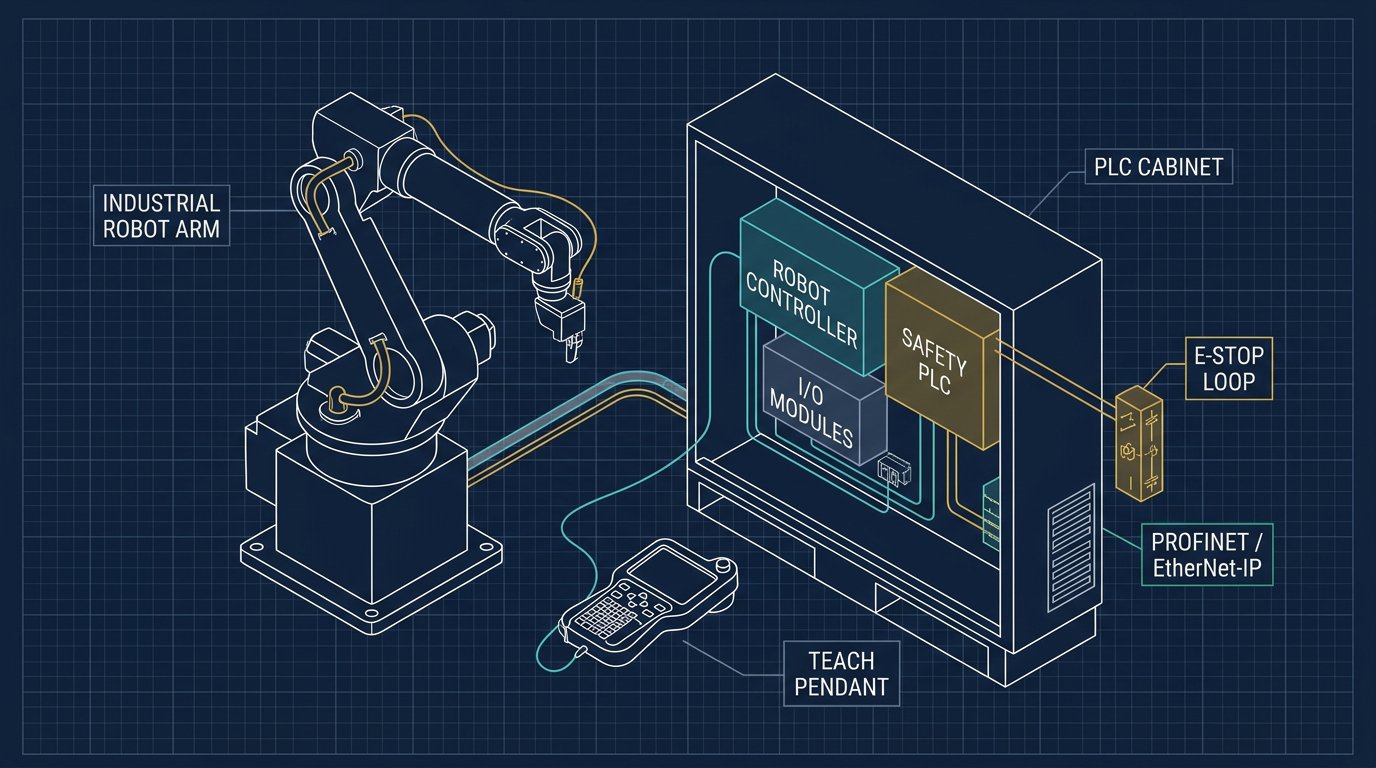
Structure of an EtherCAT ros2_control Hardware Plugin
The C++ hardware interface plugin implements four core lifecycle and execution methods:
on_init(): Parses URDF joint limits, reads drive network IDs and PDO mappings from the robot description.on_configure()/on_activate(): Initializes the SOEM master context, performs the bus scan, verifies the Reference Clock DC lock, and executes the CiA 402 state machine transitions to bring all six drives into Operation Enabled (State 4).read(): Executed at 1 kHz within the real-time thread. Callsec_receive_processdata(), extractsPosition Actual ValueandTorque Actual Valuefrom the TxPDO buffer, converts raw encoder counts to radians, and writes them to ROS 2 joint state interfaces.write(): Takes commanded joint positions (in radians) from the ROS 2 controller manager (e.g.,joint_trajectory_controller), converts radians to integer encoder counts, writes them into the RxPDOTarget Positionbuffer, and callsec_send_processdata().
// Example snippet: Real-time read/write loop in ros2_control EtherCAT hardware interface
return_type EthercatRobotHardware::read(const rclcpp::Time & /*time*/, const rclcpp::Duration & /*period*/) {
    // 1. Receive cyclic EtherCAT frame from the physical network
    int wkc = ec_receive_processdata(EC_TIMEOUTRET);
    if (wkc < expected_wkc_) {
        // Working Counter (WKC) failure indicates packet loss or slave fault
        ++consecutive_dropped_frames_;
        if (consecutive_dropped_frames_ > 3) {
            RCLCPP_FATAL(logger_, "EtherCAT communication lost! Tripping emergency stop.");
            return return_type::ERROR;
        }
    } else {
        consecutive_dropped_frames_ = 0;
    }

    // 2. Parse joint feedback from TxPDO buffers
    for (size_t i = 0; i < num_joints_; ++i) {
        int32_t raw_counts = *(int32_t*)(ec_slave[i + 1].inputs + offset_pos_actual_);
        int16_t raw_torque = *(int16_t*)(ec_slave[i + 1].inputs + offset_torque_actual_);

        // Convert raw encoder increments to radians
        joint_positions_[i] = (static_cast<double>(raw_counts) / encoder_counts_per_rev_[i]) * 2.0 * M_PI;
        joint_efforts_[i] = (static_cast<double>(raw_torque) / 1000.0) * rated_torque_nm_[i];
    }
    return return_type::OK;
}

return_type EthercatRobotHardware::write(const rclcpp::Time & /*time*/, const rclcpp::Duration & /*period*/) {
    // 1. Pack commanded joint angles into RxPDO buffers
    for (size_t i = 0; i < num_joints_; ++i) {
        int32_t target_counts = static_cast<int32_t>((joint_position_commands_[i] / (2.0 * M_PI)) * encoder_counts_per_rev_[i]);
        *(int32_t*)(ec_slave[i + 1].outputs + offset_target_pos_) = target_counts;

        // Ensure Controlword remains 0x000F (Operation Enabled)
        *(uint16_t*)(ec_slave[i + 1].outputs + offset_controlword_) = 0x000F;
    }

    // 2. Transmit frame synchronously to physical network
    ec_send_processdata();
    return return_type::OK;
}
Indicative 2026 Hardware Prices for EtherCAT Robot Arm Motion Systems
When budgeting an EtherCAT motion control architecture for an industrial or custom 6-DOF manipulator, costs divide between the central real-time compute host, industrial network interface controllers, multi-axis AC servo drive packages, and specialized flex-rated cabling. All figures below represent indicative 2026 prices in USD (with CAD reference conversions) compiled from public distributor and manufacturer documentation (Beckhoff, Leadshine, Inovance, Copley Controls, Mouser, DigiKey) as of August 2026. Industrial hardware is configuration- and quote-dependent; these figures represent representative single-unit to small-batch budgetary ranges.
| Subsystem Component | Representative Model / Spec | Key Technical Attributes | Indicative 2026 Price (USD) | Indicative 2026 Price (CAD) | Pricing Category / Basis |
|---|---|---|---|---|---|
| Industrial RT Master PC | Advantech / Beckhoff DIN-Rail IPC | Intel Core i5, 16GB DDR4, Dual Intel I210 GbE, Fanless | $1,150 – $1,850 | $1,550 – $2,500 | Distributor catalog list price |
| Single-Board Master SBC | Raspberry Pi 5 (8GB) + PCIe I210 NIC | ARM Cortex-A76, RT-PREEMPT Linux, PCIe Gen 2 NIC | $115 – $165 | $155 – $225 | Retail distributor pricing |
| Base/Shoulder Servo Drive | Leadshine EL8-EC750 / Inovance IS620N | 750W 230VAC, CoE CiA 402, DC Sync, STO SIL3 Cat 3 | $280 – $420 per axis | $380 – $570 per axis | Public OEM automation list |
| Wrist Micro-Servo Drive | Copley Accelnet Plus / Synapticon SOM | 48VDC 15A Peak, Ultra-compact PCB mount, Dual BiSS-C | $340 – $590 per axis | $460 – $800 per axis | Manufacturer quote range |
| High-Flex S/FTP Cable | Igus CFBUS.045 / Lapp Etherline Torsion | Cat5e SF/UTP, ±180°/m Torsion rated, PUR jacket (50m) | $185 – $260 | $250 – $350 | Specialty distributor list |
| Industrial Connectors | Phoenix Contact M12 D-Code Shielded | IP67 Metal screw-crimp connector set (12 units) | $140 – $190 | $190 – $260 | Electrical distributor catalog |
| Bus Coupler / Gripper I/O | Beckhoff EK1100 + EL2008 Digital Slice | EtherCAT Coupler + 8-channel 24VDC 0.5A output module | $240 – $330 | $325 – $445 | Industrial distributor list |
Troubleshooting Common EtherCAT Bus Faults in Robotic Cells
When commissioning or servicing a 6-axis manipulator, communication faults manifest rapidly due to the strict microsecond watchdog thresholds. The table below outlines a symptom-to-cause diagnostic matrix for rapid resolution in the field, expanding on our general diagnostic workflow for electrical and communication faults:
| Observed Symptom / Error | Direct Root Cause | Oscilloscope / Tool Checkpoint | Permanent Corrective Action |
|---|---|---|---|
| Working Counter (WKC) Mismatch Master reports wkc < expected |
One or more slave ESCs failed to process datagram; corrupt packet or disconnected cable downstream. | Check ESC Lost Link counters in register 0x0310-0x0313 and Rx Error counters in 0x0300-0x0307. |
Replace damaged high-flex patch lead; verify M12 connector pins for contamination or oxidation. |
| Sync Manager Watchdog Trip Drive trips CiA 402 fault 0x87A0 |
Master failed to write new cyclic output PDO before drive SM2 watchdog timer expired (typically 10 ms). | Run cyclictest on master host; verify real-time thread priority is SCHED_FIFO 98. |
Enable isolcpus in kernel boot options; disable CPU power-saving C-states; lock memory with mlockall. |
| Distributed Clock Drift Alarm Drive reports DC Sync0 PLL out of lock |
Severe clock drift on master host or corrupted ARMW drift-compensation packets caused by EMI. | Inspect physical cable routing; check for 50 mm clearance from 480V servo power cables. | Bond drive chassis to PE with 6 mm² copper braid; install ferrite chokes on inverter outputs. |
| Drive Refuses Operation Enabled Statusword stuck at 0x0040 (Switch On Disabled) |
Hardware Safe Torque Off (STO) circuit open, auxiliary 24V logic power missing, or main DC bus under-voltage. | Measure voltage across STO1/STO2 terminal pins (must be +24VDC nominal). | Verify safety relay / emergency stop circuit continuity; check main contactor status. |
Typical Reader Question: CSP vs. Profile Position Mode for Robot Arms
Typical Reader Question
"I am building a 6-axis arm. Why shouldn't I just use Profile Position Mode (PPM) or Profile Velocity Mode (PVM) and send target waypoints over EtherCAT whenever a move starts?"
Engineering Analysis: Profile Position Mode (PPM, CiA 402 Mode 1) is designed for single-axis point-to-point positioning applications, such as a conveyor indexer or a packaging feed screw. In PPM, you send a target position (e.g., Joint 1 move 90 degrees), and the internal drive microprocessor generates its own trapezoidal or S-curve velocity profile. Because each joint drive has different internal cycle rates, different payload inertias, and different servo loop gains, each axis completes its acceleration and deceleration at slightly different instants.
In a 6-DOF articulated manipulator, Cartesian motion (such as drawing a straight line or maintaining constant tool orientation) requires that all six joints trace mathematically coupled, continuous polynomial curves. If you use PPM, the Tool Center Point will deviate wildly through Cartesian space between the start and end points, risking severe collisions with fixtures and destroying toolpath accuracy. In Cyclic Synchronous Position (CSP) Mode, the central controller calculates the inverse kinematics at 1,000 Hz and dictates the exact instantaneous joint angle for every axis every millisecond, ensuring strict multi-axis path coordination, contrasting sharply with simpler digital bus servo architectures.
Safety Standards, Redundant STO & Professional Boundaries
EtherCAT provides exceptional motion determinism, but standard EtherCAT telegrams are non-safety-rated. In industrial robotic installations across the United States and Canada, machine safeguarding must comply with ANSI/RIA R15.06, CSA Z434, and ISO 10218-1/2.
To safely shut down motor power during an emergency stop, light curtain breach, or safety gate opening, robot builders must employ one of two certified architectures:
- Hardwired Dual-Channel Safe Torque Off (STO): The conventional and universally compatible approach. Each servo drive includes dedicated, hardware-isolated STO1 and STO2 input pins. An external certified safety relay (or safety PLC) drops 24V power to the STO terminals, physically disabling the gate driver optocouplers on the inverter IGBTs. This achieves ISO 13849-1 Category 3 / 4, Performance Level e (PL e) safety without relying on the real-time software stack.
- FailSafe over EtherCAT (FSoE / Safety-over-EtherCAT): An IEC 61784-3 certified functional safety protocol that encapsulates safety-critical data inside standard EtherCAT cyclic frames (the "black channel" principle). Requires certified FSoE master controllers and FSoE-enabled servo drives.
Safety Warning: Software-only commands (such as writing Controlword 0x0000 or commanding zero velocity) do NOT constitute a machine emergency stop under OSHA regulations, NFPA 79, or Canadian provincial occupational safety rules. Always implement hardwired STO circuits verified by a qualified automation engineer.
Sources and Methodology
This technical guide was compiled through analysis of published industrial automation standards and manufacturer documentation, accessed August 2026:
- EtherCAT Technology Group (ETG): ETG.1000.2 through ETG.1000.6 (EtherCAT Physical Layer, Data Link Layer, and Application Layer Protocol Specifications) and ETG.5003 (Semiconductor Device Profile).
- CAN in Automation (CiA): CiA 402-1, CiA 402-2, and CiA 402-3 (CANopen Device Profile for Drives and Motion Control / IEC 61800-7-201).
- Linux Foundation Real-Time Project: RT-PREEMPT Kernel documentation, latency measurement methodologies, and
cyclictestbenchmarking guidelines. - Industrial Component Documentation: Technical manuals, CoE object dictionaries, and hardware schematics from Beckhoff Automation (TwinCAT / AX5000), Leadshine Technology (EL8-EC series), Inovance (IS620N), and Copley Controls (Accelnet series).
Frequently asked questions
Why is EtherCAT preferred over standard CANopen for 6-axis robot arms?
Standard CANopen operates at a maximum bus speed of 1 Mbit/s, which creates a communication bottleneck when transmitting high-frequency position commands and status feedback for six or more axes. Refreshing six drives with standard CANopen PDOs typically takes 5 to 10 milliseconds, which is too slow for dynamic trajectory tracking. EtherCAT uses 100BASE-TX Ethernet at 100 Mbit/s and process data on-the-fly, allowing a master to update position, velocity, and torque for six axes in under 15 microseconds with sub-microsecond clock synchronization.
What is the difference between Cyclic Synchronous Position (CSP) and Profile Position Mode (PPM)?
In Profile Position Mode (PPM), the controller sends target coordinates and target velocities to the drive, and the drive calculates its own internal trajectory interpolation. In a multi-axis robot arm, this causes coordinate synchronization failure because each drive reaches its target independently without coordinated trajectory interpolation. In Cyclic Synchronous Position (CSP) mode (CiA 402 mode 8), the central kinematics planner computes the coordinated Cartesian-to-joint trajectory and injects new position setpoints into every drive synchronously every 1 millisecond, ensuring perfect multi-axis coordination.
Do I need a dedicated real-time operating system like VxWorks or QNX to run an EtherCAT master?
No. A standard Linux kernel patched with the RT-PREEMPT patch set (such as Ubuntu 24.04 LTS or 22.04 LTS with real-time kernel) delivers deterministic loop jitter under 15 microseconds on standard x86 industrial PCs and ARM64 single-board computers like the Raspberry Pi 5 or NVIDIA Jetson. This provides sufficient deterministic performance for 1 kHz (1 millisecond) and 2 kHz (500 microsecond) robot control loops without expensive proprietary RTOS licenses.
Why is Distributed Clocks (DC) synchronization critical for robot joint drives?
Without Distributed Clocks (DC), each servo drive samples its position command and executes its current loop at the moment it receives the Ethernet packet, which varies due to software jitter and network latency. This causes phase jitter between joint axes, resulting in path ripple and high-frequency acoustic noise. Distributed Clocks synchronizes all slave clocks to a reference clock (typically the first DC-capable slave) with sub-microsecond precision, firing the internal drive control loops simultaneously across all six joints.
What happens when an EtherCAT network cable is disconnected during robot motion?
When the EtherCAT master detects a missed cyclic frame or a broken link, the master and slave watchdog timers expire within the configured watchdog period (typically 5 to 10 milliseconds). The CiA 402 state machine in each servo drive transitions immediately to Fault Reaction Active, applies deceleration according to the configured Quick Stop ramp, trips the mechanical motor brake, and de-energizes the inverter stage into a safe torque off (STO) state.
How do I choose between the SOEM and IgH EtherCAT Master stacks?
SOEM (Simple Open EtherCAT Master) is an embeddable, user-space C library that integrates cleanly with custom C++ control applications, ROS 2 ros2_control hardware interfaces, and microcontrollers. IgH EtherCAT Master (EtherLab) is a kernel-space Linux driver that replaces standard network drivers with native real-time NIC drivers for lower CPU overhead in high-axis-count industrial controllers. For most 6-DOF robot arm projects in ROS 2, SOEM provides faster integration and easier debugging.