Disclosure and scope: this is an educational design walkthrough compiled from NFPA 79, IEC 60204-1 and related sources, not an engineered drawing and not a Robotics Engineering Lab installation report. A robot cell is a machine whose electrical system must be designed by a qualified engineer and approved by the authority having jurisdiction; use this page to understand the design, ask better questions, and verify a quotation.
Where the standard starts: NFPA 79 for the machine, NEC for the building
The first design decision is jurisdictional, and it is the one most often got wrong. In the United States, the building supply up to the machine's supply point is governed by the National Electrical Code (NFPA 70), while everything from the machine's supply disconnecting means inward — the robot controller, drives, safety circuit, field wiring, operator devices — is governed by NFPA 79, the Electrical Standard for Industrial Machinery. The current edition is NFPA 79-2024, though many jurisdictions still enforce an earlier edition, so the first line of any drawing set should state which edition the authority having jurisdiction (AHJ) enforces. Internationally, and for machines bound for Canada or export, the parallel document is IEC 60204-1:2016+A1:2021 (edition 6.1), and Canada's adoption path for robot cell safety runs through CSA Z434:26, which adopts ISO 10218-1:2025 and ISO 10218-2:2025 with Canadian deviations. Every one of those choices belongs to one coherent robot cell electrical design, and this article walks that design end to end.
The two documents agree on the architecture and differ in the details a North American panel shop lives by: conductor colors, control-circuit practice, and the certification path. A robot cell electrical design that has to satisfy both a US AHJ and a European customer therefore gets drawn once with two wiring schedules. The method below walks the supply path, the control power budget, wiring practice, and the safety circuit, with two worked calculations, so the structure of a compliant design is visible before the first wire is landed.
The supply path: disconnect, overcurrent protection, and SCCR
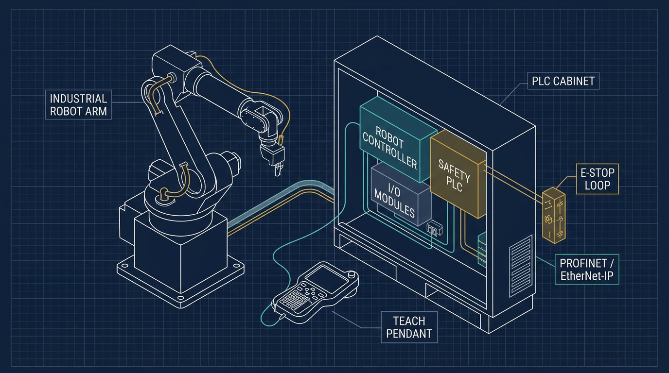
Start at the point of connection. NFPA 79 and IEC 60204-1 both require a supply disconnecting means that isolates the entire machine electrical equipment, is lockable in the open position for lockout/tagout, and interrupts the load. For a robot cell this is typically an enclosed, door-interlocked disconnect ahead of the main control cabinet. From there, branch circuits feed the robot controller, the safety circuit supply, the 24 V DC control power, cooling, and any process equipment, each with overcurrent protection sized to the conductor and the load.
Two numbers size everything downstream: the connected load and the available fault current. The connected load (often given by the robot maker in kVA) sets the full-load current; the available fault current at the panel bus sets the required short-circuit current rating (SCCR). NFPA 79-2024 explicitly addresses SCCR marking for the machine electrical equipment, and a UL 508A panel shop will not release a control panel whose marked SCCR is below the available fault current. The robot vendor's documentation is where the connected load and inrush behaviour come from — treat a missing kVA figure as a "quote required" item, not a guess.
Example calculation — stated assumptions, not a design. Assume an 8 kVA connected load on a 480 V, three-phase supply at 0.85 power factor.Recompute with the robot maker's published kVA and your utility's available fault current.
Full-load current is I = kVA × 1000 ÷ (√3 × V_LL) = 8000 ÷ (1.732 × 480) ≈ 9.6 A. Overcurrent protection and conductor ampacity are then selected from the applicable tables with their temperature and bundling corrections, and the disconnect and branch devices must carry a rating above the continuous load with margin. The point of the arithmetic is not the 9.6 A; it is that every downstream choice — conductor, breaker, disconnect, and the SCCR coordination — traces back to a connected load and a fault current that must be obtained, not assumed.
Control power: the 24 VDC budget that keeps the safety circuit honest
The most common robot-cell electrical failure we hear described is a 24 V DC supply loaded to its limit, so that a simultaneous brake release and valve strike sags the rail and drops the safety relay or a field device. The fix is a control-power budget, drawn like a current ledger, before the supply is chosen.
| Load | Assumed current at 24 VDC | Note |
|---|---|---|
| Safety relay / safety PLC logic | 0.2–0.5 A | Dual-channel, monitored |
| Robot controller I/O and field bus | 0.5–1.5 A | Per controller datasheet |
| Solenoid valves, pneumatic package | 0.1 A each | Multiply by valve count, include inrush |
| Stack light, indicators | 0.05–0.2 A | LED devices are small |
| Area scanner / light curtain OSSD load | Per device datasheet | Often on a dedicated supply |
Sum the steady load, add inrush for the worst simultaneous start, then apply margin — a common practice is to load a switching supply to no more than about 80 percent of rating so it survives ambient heat and future additions. A small cell might land near 3–5 A at 24 V; a larger cell with valves and safety field devices can need 10 A or more, or a split rail so a field short cannot drag down the safety logic. Indicative 2026 reference prices for the supply itself: a Mean Well HDR-60-24 (24 V, 2.5 A) lists at 20.10 USD at DigiKey, while a diagnostic-capable industrial supply such as a Phoenix Contact QUINT4-PS at 2.5 A lists near 193.91 USD at DigiKey — the price gap buys condition monitoring and DC-OK signalling, which is exactly what a fault log wants. Prices are reference ranges from public distributor listings accessed August 26, 2026, not Robotics Engineering Lab inventory.
Robot cell electrical design wiring practice: conductor colors, grounding, EMC
Conductor identification is where NFPA 79 and IEC 60204-1 visibly diverge, and it is a frequent finding on imported machines. NFPA 79 expects black ungrounded line conductors, white or gray for the grounded (neutral) conductor, and green or green/yellow for the equipment grounding conductor; IEC 60204-1 expects brown/black/gray for lines, blue for neutral, and green/yellow for protective earth. The 2024 NFPA 79 edition also identifies DC circuits that remain energized with the main disconnect open as orange with a blue stripe — a small detail that prevents a nasty surprise during lockout. Grounding is a single bonded system: the equipment grounding conductor, the cabinet bonding, and the robot base bond all return to one point, and high-frequency noise problems almost always trace to a grounding scheme that created parallel paths.
Electromagnetic compatibility is the second silent requirement. IEC 60204-1's EMC provisions and NFPA 79's wiring rules both push the same practice: separate sensitive signal and field-bus cables from motor and drive cabling, use shielded encoder and resolver cables with the shield landed correctly at one or both ends per the drive manual, and keep variable-frequency drive output runs away from the safety circuit. A robot cell is a noisy electrical environment by construction; the cabling plan is what keeps the network and the encoders honest.
The safety circuit: dual-channel design, PL r, and where the robot controller fits
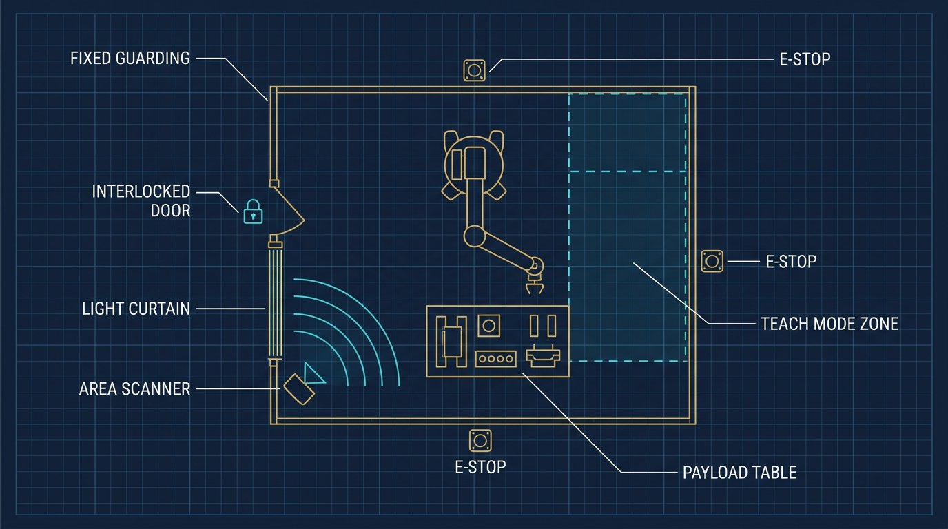
The safety circuit is not part of the standard control system; it rides above it on its own architecture. E-stop chains, interlocked door switches, and area-scanner OSSD outputs feed a safety relay or safety PLC, whose outputs remove drive power or command a safe stop category at the robot controller. The required performance level (PL r) comes from the risk assessment per ISO 13849-1:2023 (or IEC 62061), and the achieved structure — dual-channel with monitored discrepancy, correctly rated contacts, and a defined fault reaction time — is what you verify against it. Our e-stop design guide and light curtain guide cover the device side; the electrical-design point here is that the safety circuit gets its own supply, its own wiring rules, and its own verification test, and it is never the place to economize.
The robot controller's role is to receive the safety demand and execute the correct stop category — a category 0 removal of power, a category 1 controlled stop with power then removal, or a category 2 controlled stop with power maintained — exactly as the risk assessment specifies. The handshake between the cell safety circuit and the robot controller, and the division of responsibility with a plant PLC, is the subject of our PLC integration guide; electrically, the interface is a defined set of safe inputs and outputs whose wiring and timing must match the robot maker's integration manual word for word.
Example calculation: voltage drop on a long robot-cell run
Example calculation — planning arithmetic with stated assumptions; confirm against the ampacity and voltage-drop rules of the edition your AHJ enforces.Uses the dc resistance published in NEC Chapter 9, Table 8 (about 1.93 ohm per 1000 ft for 12 AWG uncoated copper).
Assume a 20 A, 480 V three-phase branch run of 100 ft to a controller, on 12 AWG copper. Line-to-line drop is approximately √3 × I × R_line, with R_line = 1.93 ohm/kft × 0.1 kft = 0.193 ohm. That gives √3 × 20 × 0.193 ≈ 6.7 V, or about 1.4 percent of 480 V — acceptable against the common 3 percent design target. The same arithmetic shows why long runs at low voltage are the trap: the same 20 A at 24 V DC on a thin conductor is a disaster, which is exactly why 24 V field power is distributed with heavier conductors or localized supplies. Voltage drop is not a code violation by itself in every case, but it is a reliability specification, and a controller that browns out at the end of a long run is an electrical design fault, not a robot fault.
Typical reader question: can I keep my 120 V AC control circuit?
Typical reader question: "Our older cells use 120 V AC control circuits. Do we have to convert to 24 V DC for a new robot cell?"Answered from the standards' structure, not from a survey we ran.
Not automatically. NFPA 79 permits 120 V AC control circuits under defined conditions (typically derived from a control transformer with a grounded side and appropriate overcurrent protection), which is why legacy North American machinery carries them. IEC 60204-1 strongly prefers low-voltage DC control, and modern robot and safety-field-device integration is overwhelmingly 24 V DC because the devices — scanners, curtain OSSDs, safety relays, field bus — are DC devices. The practical answer for a new robot cell is 24 V DC for control and safety, with 120 V AC reserved for convenience outlets and lighting circuits; the conversion question only really arises on retrofits, where the risk assessment and the integration manual decide.
Commissioning and verification: what an AHJ and a panel shop will look at
Verification is where the design becomes evidence. Expect the panel to be marked with its SCCR and the machine supply ratings; expect the disconnect to be lockable and labelled; expect the grounding system to be continuity-tested end to end; expect the safety circuit to be function-tested including a discrepancy fault injected on one channel; and expect the e-stop and interlock functions to be proven by measurement, not by assumption, with stop times recorded against the risk assessment. For a US-listed panel the certification path is typically UL 508A for the control panel plus NFPA 79 for the complete machine electrical system — a listed panel is a major component of compliance but does not by itself certify the machine. Our PLC integration commissioning checklist covers the controls side of the same visit.
Scope, safety, and professional boundaries
Robot cell electrical work is live-energy work by definition during commissioning and is lockout/tagout work during maintenance; OSHA 29 CFR 1910.147 and 1910.333, and NFPA 70E for arc-flash and shock safety during energized work, govern the people doing it. This page is educational: it does not approve a design, and it does not replace the engineer of record, the AHJ, or the robot maker's integration manual. In Canada, provincial electrical codes and CSA Z434:26 set the parallel requirements. Where any of this touches a safeguarding or safety-rated function, the risk assessment and a qualified professional are the authority, not an article.
Sources and methodology
Architecture and requirements follow NFPA 79-2024 (Electrical Standard for Industrial Machinery) and IEC 60204-1:2016+A1:2021 (edition 6.1), with panel certification per UL 508A; performance levels per ISO 13849-1:2023; Canadian adoption per CSA Z434:26 (adopting ISO 10218-1:2025 and ISO 10218-2:2025) and CSA Z434.1:26; workplace electrical safety per OSHA 29 CFR 1910.147, 1910.333 and NFPA 70E. Conductor resistance from NEC Chapter 9, Table 8. Component reference prices from public DigiKey listings (Mean Well HDR-60-24 at 20.10 USD; Phoenix Contact QUINT4-PS at 24 V/2.5 A near 193.91 USD) and the NFPA 79-2024 printed edition at 139.00 USD from a US standards retailer, all accessed August 26, 2026 and labelled as reference, not quotation. Robotics Engineering Lab did not build or energize a cell for this article; all scenarios and calculations are illustrative with stated assumptions.
Frequently asked questions
Which standard governs a robot cell's electrical system in the USA?
From the machine's supply disconnecting means inward, NFPA 79, the Electrical Standard for Industrial Machinery, with the current edition NFPA 79-2024; the building supply up to that point is governed by the NEC, NFPA 70. Check which edition your authority having jurisdiction enforces, because adoption lags publication.
What is SCCR and why does my robot panel need it?
The short-circuit current rating is the fault current the electrical equipment can safely withstand. NFPA 79-2024 and UL 508A require the panel and the machine electrical equipment to be rated at or above the available fault current at the line terminals; a panel whose marked SCCR is below the available fault current cannot be released by a UL panel shop.
How big should the 24 VDC control power supply be for a robot cell?
Budget the steady current of the safety logic, controller I/O, valves and indicators, add the worst simultaneous inrush, and load the supply to about 80 percent of rating for heat and future margin. A small cell lands near 3 to 5 A and a valve-heavy cell can need 10 A or a split rail so a field short cannot drag down the safety logic.
Why are my robot cell's field-bus and encoder readings noisy?
Usually an EMC or grounding fault: motor and drive cabling running parallel to signal cables, encoder shields landed incorrectly, or a grounding scheme with parallel paths. Separate power and signal routes, use shielded feedback cabling per the drive manual, and bond to a single point; IEC 60204-1's EMC provisions and NFPA 79 wiring rules both push this practice.
Can a robot cell keep a 120 V AC control circuit?
NFPA 79 permits 120 V AC control circuits under defined conditions, which is why legacy machinery has them, but modern robot and safety-field devices are 24 V DC devices and IEC 60204-1 prefers low-voltage DC. New robot cells are usually 24 V DC for control and safety, with 120 V AC reserved for outlets and lighting; retrofits decide case by case.
Who is allowed to commission robot cell electrical work?
Qualified persons under the applicable rules: a licensed or qualified electrician for line and branch work, and qualified personnel for energized verification under NFPA 70E and OSHA 1910.333, with lockout/tagout per OSHA 1910.147 for maintenance. The design itself should be sealed by the engineer of record and accepted by the authority having jurisdiction; this article is educational and approves nothing.