
Disclosure and scope: this is a diagnostic method, not a report of a Robotics Engineering Lab test bench. We have not reproduced these faults on our own hardware; the alarm behaviour described follows public controller documentation (ABB, FANUC, Universal Robots) and standard practice, and the scenarios are labelled as illustrative. On an industrial cell, fault-finding inside the safeguarded space is maintenance work and must follow your lockout/tagout procedure and the current edition of the applicable standard.
Why robot arm troubleshooting fails without a fault-domain map
Most wasted hours in robot arm troubleshooting come from guessing instead of separating. A robot that misses a pick can be wrong in the electrical layer (a sagging 24 V rail), the mechanical layer (worn reduction gearing), the software layer (a retuned controller or a changed tool frame), or the safety layer (a nuisance e-stop or scanner fault). Those four domains produce overlapping symptoms, so the discipline that saves time is to decide which domain you are in before you open a panel or touch a wrench. This article gives you that separation as a method, with a symptom-to-cause table, the measurements that prove each diagnosis, and the pass criteria that tell you when to stop.
The method is the same one good maintenance teams already use on CNC machines and presses: reproduce the symptom safely, then walk the domains in a fixed order — electrical first, because it is the cheapest to check and the most common cause of intermittent faults; then software and configuration, because a changed parameter masquerades as hardware; then mechanical, because drivetrain wear is slow and shows up as drift; and finally the safety circuit, because a marginal e-stop contact or scanner alignment causes the most confusing intermittent stops.
Two references anchor the method. For the formal maintenance and verification context of an industrial cell, ISO 10218-2:2025 (and its US adoption ANSI/A3 R15.06-2:2025) places maintenance, periodic verification and information-for-use responsibilities on the integrator and the end user, which is exactly why a documented fault log matters. For the measurement side, ISO 9283:1998 defines how pose accuracy and repeatability are specified and tested, which is the tool we use below to separate a software problem from a mechanical one. Where the work requires live electrical measurement or entry into a guarded cell, OSHA 29 CFR 1910.147 (control of hazardous energy) and your local rules govern, and a qualified electrician or controls engineer should do the work.
Symptom: the robot will not move — a triage order that never lies
Start with the state the controller reports, not the behaviour you assume. Read the active fault, the active mode, and whether any safety input is open. A robot that will not move is almost always telling you the answer on the pendant: an open e-stop chain, an open interlock, a drive-not-ready, or a mastering-not-established condition. Record the exact message before you clear anything, because the fault log is your only reliable witness after the reset.
Then verify the electrical domain from the outside in. Confirm the incoming supply at the disconnect, the status of the branch protective devices, and the control power rail. A 24 V DC control rail loaded near its limit will sag during a brake release or a valve strike and produce intermittent no-move or drive-fault conditions that disappear when the multimeter is connected. Measure the rail under the worst-case simultaneous load, not at idle, and watch for dips below the device brown-out threshold during the first second after power-up, when brakes and contactors inrush together.
- No power at the pendant: work back from the controller supply, through the main disconnect and any door interlocks, before suspecting the pendant.
- Power but drive not ready: check the e-stop chain continuity and the safety relay or safety PLC status indicators; a single open dual-channel contact holds the whole cell.
- Ready but motion faults immediately: suspect mastering, encoder feedback, or a brake that did not release, in that order.
The classic electrical failure mode worth knowing by heart is the encoder backup battery. Absolute encoders hold their position reference on a battery while the controller is off. ABB product manuals document a battery-low alert (for example event 38213 on several IRB manuals) and state the battery lifetime depends on how long the robot is powered off — the IRB 6650S product manual gives roughly 36 months with typical weekend shutdowns and about 18 months with long daily off periods. FANUC documents the equivalent as a battery-alarm condition (BZAL) that, if ignored, leads to a lost absolute reference and a required re-establishment step per axis. The practical rule is identical across brands: treat a low-battery alarm as urgent, keep control power on until the swap is complete, and never change batteries with the controller off unless the manual says otherwise.
Symptom: position drift and lost mastering
Position drift splits into two very different faults: the robot is consistently wrong (a datum problem) or the robot is inconsistently wrong (a mechanical or feedback problem). A consistent offset that appeared after a crash, a battery fault, or a motor replacement is a mastering or tool-frame issue, not wear. An inconsistent offset that grows through the day is thermal or mechanical.
For the datum case, verify mastering against a known physical reference — a mastering fixture, a dowel, or the quick-mastering marks the manufacturer provides — and confirm the tool center point (TCP) and work object frames against the values the cell was commissioned with. A TCP that was re-taught by someone and never documented is a surprisingly common cause of a cell that is "off by a few millimetres everywhere." Our calibration guide covers mastering and error correction in depth; here the diagnostic point is simply that a uniform offset points to data, not hardware.
For the inconsistent case, log position error against time and temperature. Thermal growth in the arm structure and in reduction gearing shifts the real TCP even when the encoders read perfectly. If the drift tracks ambient or duty cycle and recovers after a cool-down, you are looking at thermal behaviour, and the correction belongs in the cycle plan and duty-cycle design (see our cooling guide if heat is the driver), not in a re-master that will just move the error.
Illustrative scenario — not a report of a Robotics Engineering Lab test. A cell runs fine on Monday, is off over the weekend, and on Monday morning reports a lost absolute reference on two axes.The sequence matches the documented battery-failure path: low-battery warning ignored, weekend power-off, absolute reference lost, axes require re-establishment and a mastering check. The fix is procedural as much as technical.
Symptom: jitter, vibration and noise under load
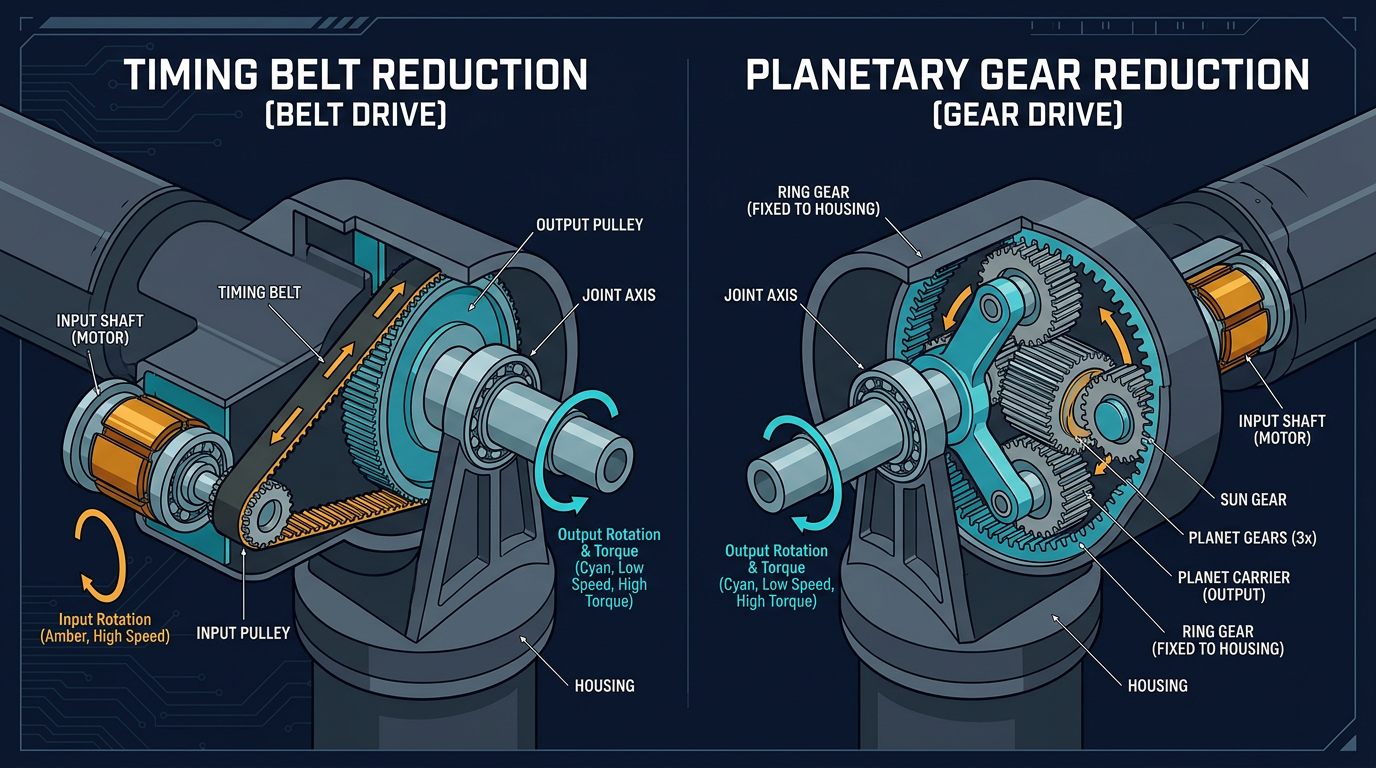
Vibration that appears under load but not at idle points at the drivetrain: reduction gearing, belts, bearings, or a loose mechanical interface. Vibration that appears at specific Cartesian speeds regardless of load more often points at control tuning or at a singularity region. Our encoder guide and our transmission comparisons explain the components; the diagnostic here is to localize the noise by feel and by listening with the cell safe and the robot jogging slowly in each axis individually, so the guilty joint identifies itself.
- Whine that rises with joint speed: typically gearing or a dry bearing; check lubrication interval against the manufacturer's schedule, which our maintenance guide summarizes.
- Knock or clunk at direction reversal: backlash in a reduction stage or a loose set-screw / coupling; measure with a dial indicator at the output while holding the input, not by eye.
- Buzz at a fixed frequency at the wrist: often a resonant fixture or EOAT, not the robot; test by repeating the move with the tool removed.
A worn harmonic or cycloidal reducer shows up first as lost-motion growth and as vibration under reversing load, long before it shows up as a position alarm. Trending backlash at a fixed inspection interval is therefore one of the highest-value predictive checks a maintenance team can do on an older arm.
Symptom: following error and thermal faults at speed
A following-error or overcurrent fault that appears only at high speed or high acceleration is the controller telling you the demanded torque exceeds what the drive can deliver. The cause is mechanical (a stiff or binding joint, an overweight tool), thermal (a motor or drive derated by heat), or a tuning change. Check the tool data first: a TCP mass or inertia entered wrong, or a real tool that grew heavier than the commissioned value, makes every fast move an overload. Then confirm payload and inertia settings match the actual end effector plus part, using the sizing math in our payload resource if you need it.
If the fault appears late in a shift and not at the start, thermal derating is likely. Log drive and motor temperature against cycle count; a rising baseline means the cooling path is inadequate for the duty cycle. The fix is either a slower cycle, a longer dwell, better airflow, or a robot with more thermal margin — not a higher current limit, which trades an alarm today for a burned winding tomorrow.
Symptom: safety circuit faults and nuisance stops
Nuisance e-stops and scanner faults are electrical in origin but safety in consequence, so they get their own domain. The signature is an intermittent open on a dual-channel circuit: the safety relay sees a channel mismatch and holds the stop until reset, or a scanner reports a fault on vibration or a dirty window. Check the e-stop chain contact by contact, because a single marginal contact produces a fault that no software log explains, and verify scanner alignment and lens cleanliness against the manufacturer's procedure. Our e-stop design guide explains the dual-channel architecture you are measuring. Never bypass a safety input to "prove" it is the cause; the proof comes from measuring contact resistance and channel timing, not from defeating the circuit.
Example calculation: is the repeatability drift mechanical or software?
Example calculation — planning arithmetic with stated assumptions, not a measurement from our bench.Use ISO 9283:1998 test methods and your own laser tracker or ball-bar data before acting on the conclusion.
Suppose a cell was commissioned at pose repeatability of ±0.05 mm and now a quality check reports ±0.18 mm at one pose but ±0.05 mm everywhere else. ISO 9283 defines repeatability as the closeness of agreement between repeated poses under the same conditions, so the first separation is repeatability (scatter) versus accuracy (offset). If the pose is consistently offset by 0.13 mm with the same scatter as before, the datum or tool frame moved — a software/data fault. If the scatter itself grew, something physical changed in that joint's path — gearing, bearing, or a loose interface.
Now localize with a simple moment argument. Assume the affected pose fully extends joint 3, whose output carries the forearm at about 0.6 m. A backlash growth of only 0.0002 rad (about 0.011 degrees) at that joint produces roughly 0.6 m × 0.0002 rad ≈ 0.12 mm of TCP scatter — exactly the observed growth. A sub-arcminute change in lost motion is entirely plausible for a worn reduction stage, which is why the calculation points at the mechanical domain and a dial-indicator backlash check, not at re-tuning. The numbers are assumptions for illustration, but the method — convert an angular error at a joint to a linear error at the TCP by the lever arm — is the correct way to decide whether a repeatability complaint is drivetrain wear.
A fault log that pays for itself
The difference between a cell that is diagnosed in minutes and one that is diagnosed in hours is almost always documentation. Keep a per-cell fault log with the exact controller message, the domain it mapped to, the measurement taken, the value found, and the fix. Log battery voltages and dates, backlash measurements with dates, and any TCP or frame re-teach with the author and the reason. Over a year this log becomes the single most valuable asset in the maintenance program, because intermittent electrical faults are only visible as a pattern across events.
| Symptom | First domain | Likely cause | Test / evidence | Pass criterion |
|---|---|---|---|---|
| Will not move | Electrical / safety | Open e-stop or interlock, drive not ready, dead control rail | Read active fault; measure 24 V rail under load | All safety inputs closed; rail within device spec at inrush |
| Lost position after power-off | Electrical | Encoder backup battery discharged | Battery voltage and alarm history | Battery above threshold; reference re-established; mastering verified |
| Uniform offset everywhere | Software / data | TCP or work object frame changed; mastering datum wrong | Compare frames to commissioning record; check against fixture | Offset removed without mechanical change |
| Scatter grows at one pose | Mechanical | Backlash / bearing wear at a specific joint | Dial indicator backlash; ISO 9283 repeatability trend | Scatter within commissioned band after repair |
| Thermal or overcurrent fault late in shift | Software / thermal | Wrong tool inertia; inadequate cooling for duty cycle | Tool data audit; drive temperature trend | No derate over a full shift at production rate |
| Intermittent stop, channel mismatch | Safety circuit | Marginal e-stop contact; scanner misalignment | Contact resistance; scanner alignment check | No mismatch over a fixed observation window |
When to stop: escalation and the qualified professional
Robot arm troubleshooting has a hard boundary. Anything that requires entering the safeguarded space with energy present, opening a drive cabinet, modifying a safety circuit, or re-mastering an industrial robot that people work near is work for a qualified maintenance technician, controls engineer, or integrator under the site's lockout/tagout and risk-assessment controls. The diagnostic method in this article is for understanding the fault, gathering evidence, and communicating precisely with the professional who will fix it — a fault log with measurements turns a service visit from a guessing exercise into a scoped repair. On hobby and educational benches the same method applies at bench scale, with a physical power switch and hard stops, and nothing here constitutes a safety approval of any cell.
Sources and methodology
The fault-domain method follows standard industrial maintenance practice. Encoder battery behaviour follows ABB product manual wording (for example the IRB 6650S product manual 3HAC020993-001, "Replacing the SMB battery," including the 36/18-month lifetime figures and the 38213 battery-low event) and FANUC's documented battery-alarm and pulse-not-established sequence; verify exact alarm wording in the manual edition shipped with your controller. Performance separation of accuracy and repeatability follows ISO 9283:1998. Maintenance and verification responsibilities follow ISO 10218-2:2025 and ANSI/A3 R15.06-2:2025; end-user use follows ANSI/A3 R15.06-3-2025; lockout/tagout follows OSHA 29 CFR 1910.147. Sources accessed August 26, 2026. Robotics Engineering Lab did not reproduce these faults on hardware before publication; scenarios are illustrative and labelled.
Frequently asked questions
What is the first thing to check when a robot arm will not move?
Read the active fault on the pendant before touching anything, then verify the safety inputs and the 24 V control rail under load. An open e-stop chain, an open interlock or a sagging control rail cause most no-move conditions, and the fault log is your only reliable witness after a reset, so record the exact message first.
Why does a robot lose position after a weekend power-down?
Absolute encoders hold their position reference on a backup battery while the controller is off. If the battery is low and the controller stays off long enough, the reference is lost and the axes must be re-established and mastering verified. ABB and FANUC both document low-battery warnings that should be treated as urgent, with the swap done while control power is on.
How can I tell if repeatability drift is mechanical wear or a software problem?
Separate scatter from offset using ISO 9283 definitions. A consistent offset with unchanged scatter points to a datum, TCP or work-object frame change. Grown scatter at a specific pose points to backlash or bearing wear in one joint; converting the angular error to a TCP error by the lever arm tells you whether the magnitude matches drivetrain wear.
What causes following-error faults only at high speed?
The drive is being asked for more torque than it can deliver at that speed. Check the tool mass and inertia data first, since a wrong or grown tool load makes every fast move an overload, then look at thermal derating if the fault appears late in a shift, and at binding or an overweight fixture if it is constant.
Is it safe to bypass a safety input to find an intermittent stop?
No. Bypassing defeats the protection and changes the legal status of the cell. Prove a marginal contact by measuring contact resistance and dual-channel timing, check scanner alignment and lens condition against the manufacturer procedure, and keep the circuit intact while you measure. Nuisance stops are diagnosed with the circuit in service, not defeated.
When should troubleshooting stop and a professional take over?
Whenever the work requires entering a safeguarded space with energy present, opening a drive cabinet, modifying a safety circuit, or re-mastering an industrial robot that people work near. Those are tasks for a qualified maintenance technician, controls engineer or integrator under lockout/tagout and the site risk assessment; the fault log you build makes that visit faster and cheaper.