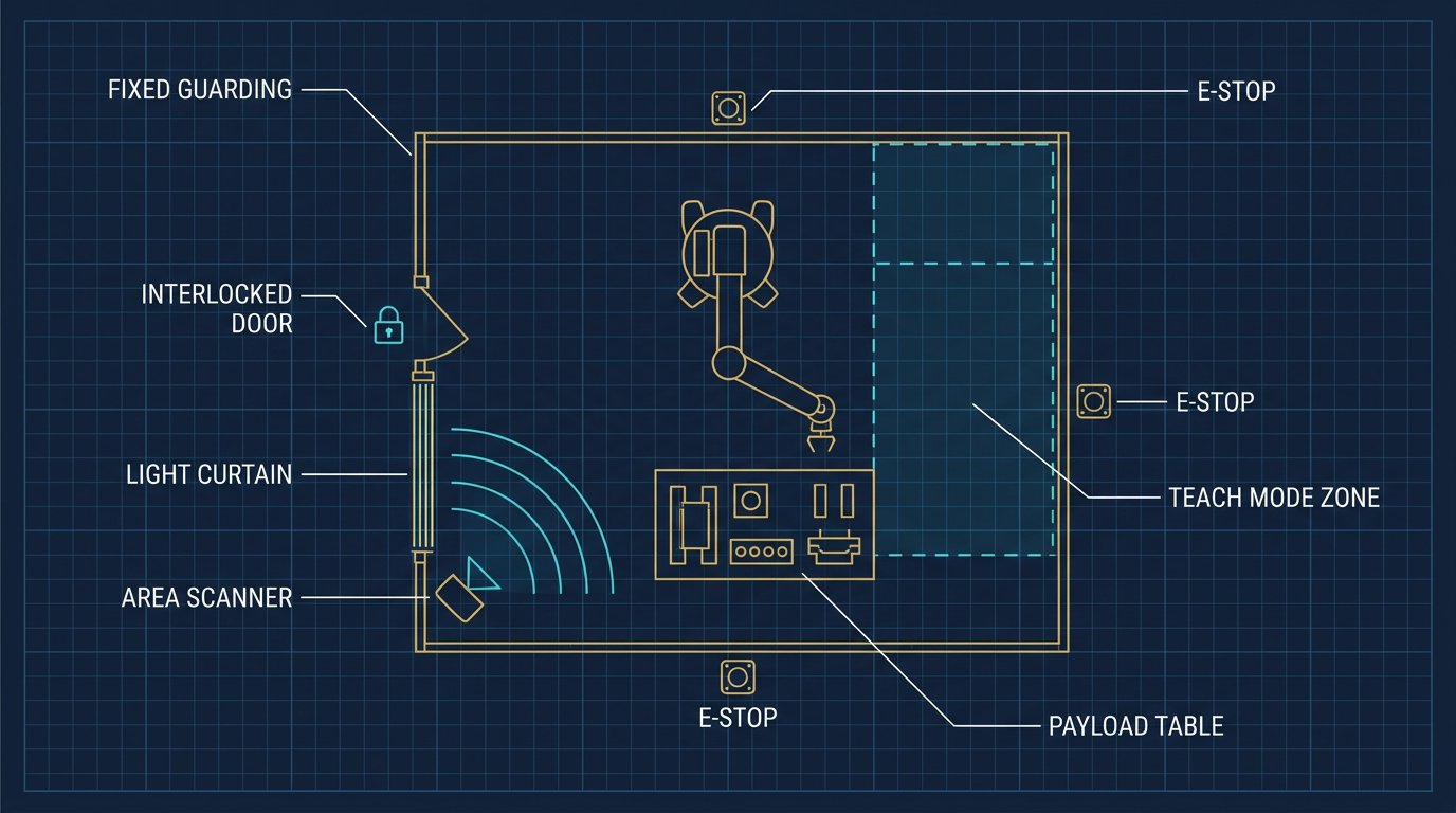
Disclosure and scope: this is an educational validation procedure, not a certification and not a report of a Robotics Engineering Lab measurement campaign. Force and pressure limits are legal-adjacent safety requirements; the risk assessment, the integrator, and the current edition of the applicable standard are the authority. We did not run a measurement campaign for this article.
Cobot force limit validation is the instrumented proof that a collaborative robot application stays below the biomechanical force and pressure thresholds a person can experience at a contact point. It is the part of a collaborative cell project that turns a brochure claim into a defensible engineering file, and it is the part most often skipped until an integrator, an insurer, or a regulator asks for the numbers. This article is a validation procedure: it follows the standards stack as it stands in 2026, separates the two kinds of contact that must be measured, and ends with the content of a report that survives review.
What changed in 2025 and 2026: the standards stack for collaborative force limits
For nearly a decade the number integrators reached for on collaborative force was ISO/TS 15066:2016. That document still exists — ISO's catalogue lists it as published and under revision, with a successor (ISO/AWI 15066-1) in development — but its practical home has moved. ISO 10218-1:2025 and ISO 10218-2:2025, published in February 2025, absorbed the collaborative-application safety requirements, so the force and pressure limits now live inside the core robot-safety standard rather than in a separate technical specification. In the United States, ANSI/A3 R15.06-2025 (Parts 1 and 2) adopts the ISO 2025 editions, and ANSI/A3 R15.06-3-2025 adds the end-user requirements with no ISO counterpart. In Canada, CSA Z434:26 adopts ISO 10218-1:2025 and ISO 10218-2:2025 with Canadian deviations, alongside CSA Z434.1:26 for end users.
The practical consequences for a validation file are three. First, new documentation should cite ISO 10218-2:2025 (and the applicable national adoption) as the primary collaborative reference, with ISO/TS 15066:2016 retained as historical context where a cell was commissioned against it. Second, collaboration is now framed as a property of the application, not of the robot: a power-and-force-limited arm carrying a sharp or heavy tool is not a collaborative application no matter what the brochure says. Third, the body-region biomechanical thresholds — the table of force and pressure limits by body area — survive the move essentially unchanged, which is why existing measurement data usually remains valid while the paperwork trail is updated. RIA TR R15.806 remains the US technical report describing how to actually perform power-and-force-limiting contact testing; read its 2018-era terminology against the 2025 renames.
The four collaborative modes, and why PFL is the one you validate with instruments
The standards recognize four collaborative techniques: safety-rated monitored stop, hand guiding, speed and separation monitoring, and power and force limiting. The first three are largely validated by function — the stop works, the enabling device behaves, the separation distance is maintained — and by safeguarding geometry. Power and force limiting (PFL) is different because its safety argument is a number: the force and pressure that a person can experience at a contact point must stay below the biomechanical threshold for the body region that contact can reach. A number that must stay below a limit is a number you must measure, which is why PFL is the mode that produces an instrumented validation report.
PFL also has the sharpest boundary of the four: it applies to the contact scenarios the risk assessment identifies, including the end effector and the part. The robot may be force-limited, but the application is only collaborative if the tool and part geometry — edges, corners, pinch points, mass — keep the transient and quasi-static contacts within limits. Our end-effector selection guide is where the tool's mass and geometry enter the payload and frame math; here they enter as the thing being pressed against a person.
Quasi-static versus transient contact: the two cases the test must cover
Every PFL contact scenario is classified as either quasi-static or transient, and the limits differ. A quasi-static contact is one in which a body part is clamped between the robot and a fixed object — the robot keeps pushing against a trapped hand, for example — so the limit is a sustained force and pressure the body region can tolerate. A transient contact is a brief impact or brush, where momentum and contact duration matter and higher peak values are permitted for a short time. The validation must consider both for each identified contact location, because a point that is harmless in transient contact can be hazardous if a person can be clamped there.
The thresholds themselves are organized by body region — head, neck, shoulder, arm, hand, fingers, trunk, leg, and so on — with a force limit in newtons and a pressure limit in newtons per square centimetre for each. The underlying principle published with ISO/TS 15066 is that the allowable values are derived from pain-threshold data with a margin, so the limits are biomechanical, not arbitrary. We do not reproduce the threshold table here, because quoting limit values from memory is exactly how a validation file gets it wrong; the correct move is to read the table in the current standard for the specific body regions your contact map reaches, and to let the measurement system's software apply the right limit per region.
The test equipment for cobot force limit validation: force and pressure measurement
A PFL measurement is made against a body-part surrogate: a spring-loaded, instrumented probe that presents a defined contact area and compliance, so the recorded force and pressure approximate what a human tissue region would experience. Commercial PFL test systems integrate a force sensor and a pressure-sensitive film or matrix with software that captures the peak force, peak pressure, and contact duration for each impact. What matters for a defensible report is not the brand but the metrology: a stated measurement uncertainty, a sampling rate high enough to capture transient peaks, a defined contact area for pressure, and a calibration traceable to a national standard. Rental houses and third-party validation firms exist precisely because a compliant measurement system is a specialized, quote-required purchase rather than a shelf item.
Plan the mechanical setup before the first hit. The surrogate must be held rigidly at the contact location, oriented normal to the expected contact direction, and the robot must run the real production motion at the real speed and force settings — a validation run at reduced speed proves almost nothing. Where a quasi-static clamp is possible, the test must reproduce the worst-case trapped geometry, including a fixture edge or an adjacent machine, because the clamp partner defines the pressure distribution as much as the robot does.
Stage 1: scope the contact scenarios from the risk assessment
The validation does not start at the robot; it starts in the risk assessment, which our risk assessment guide walks through. Extract every task in which a person is intended or reasonably foreseeable to be inside the collaborative workspace — loading, hand-off, clearing a jam, teaching — and for each, list the body regions that can be contacted and whether the contact is transient or can become quasi-static. This list is the test plan. A cell whose risk assessment says "no intended contact" still needs a PFL validation if a foreseeable misjudgment can produce contact, because PFL is also the fallback that keeps an unintended contact from becoming an injury.
Stage 2: map worst-case contact locations on the robot, tool and fixture
For each scenario, mark the contact points on the robot, the end effector, the part, and the surrounding fixtures that could form a clamp. Include the tool's sharpest edge and the part's corners, not just the robot's smooth surfaces, and include the wrist and elbow where the geometry concentrates force. The map is a drawing or photo set annotated with numbered points, and each point carries the body region it can reach and the contact type. This is the stage where most under-scoped validations fail later: a report that measured only the tool face and never the wrist is incomplete the day someone reaches past the wrist.
Stage 3: measure force and pressure against the body-region thresholds
At each mapped point, run the production motion and record peak force and peak pressure, separating transient from quasi-static as the scenario dictates, and compare against the threshold for the body region that point can contact. Repeat enough times to be statistical — a single hit is an anecdote — and record the robot speed, force setting, and tool configuration with every result so the report is reproducible. Any point that exceeds its threshold is a finding, not a footnote: the remedies are lowering speed or force, padding or rounding the geometry, re-positioning the contact out of reach, or re-classifying the application as non-collaborative with added safeguarding.
Illustrative scenario — not a report of a Robotics Engineering Lab test. A 12 kg cobot hands a 1 kg part to an operator at chest height; the risk assessment identifies transient contact at the forearm and a possible quasi-static clamp between the part and a shelf edge.The validation measures both the forearm transient impact and the worst-case clamp at the shelf edge, at production speed, and compares each to the current standard's forearm and hand thresholds.
Stage 4: document, cap, and re-validate after any change
The deliverable is a validation report that ties every measurement to a scenario, a contact point, a body region, a threshold, and a pass/fail, with the measurement uncertainty stated and the instrument calibration referenced. Critically, the report also records the configuration that was validated — robot model and software version, tool, part, speed and force settings — because a PFL validation is a snapshot. Any change to the tool, the part, the speed, the force limit, the layout, or the robot software voids the snapshot and demands at least a targeted re-validation. Write that rule into the cell's change-control procedure so the validation stays true over the cell's life.
Speed and separation monitoring: the separation-distance calculation
Example calculation — planning arithmetic with stated assumptions; the current standard gives the exact terms and your risk assessment sets the inputs.Recompute with measured stopping distances and the approach speeds you actually allow.
Where collaboration is by speed and separation monitoring rather than by force, the protective separation distance S is the sum of contributions: the distance the person covers during the system reaction and stop (S_p and the human approach speed term), the distance the robot travels during its stopping time (S_r, from measured stopping performance), plus allowances for sensing uncertainty and intrusion (C, Z_d, Z_a). As a worked illustration, assume a human approach speed of 1.6 m/s, a robot stopping time of 0.4 s with an average stopping speed that yields about 0.35 m of travel, and combined sensing and intrusion allowances of 0.25 m; with the person's contribution over the same reaction window at roughly 0.65 m, the protective separation distance lands near 0.65 + 0.35 + 0.25 ≈ 1.25 m. The arithmetic is illustrative, but the structure is the point: SSM is validated by measured stopping distance and by the scanner or curtain geometry, and it interacts with PFL because a contact that occurs after the separation is breached falls back onto the force limits.
What a validation report must contain
A defensible report carries the standards and editions cited, the risk-assessment scenarios, the contact-point map with body regions and contact types, the instrument model and calibration certificate, the measured peak force and pressure per point with uncertainty, the thresholds applied per body region, pass/fail with margin, the validated configuration (tool, part, speeds, forces, software versions), and the re-validation triggers. For a US cell, RIA TR R15.806 is the methodological reference; for Canada, CSA Z434:26 and Z434.1:26 set the adoption and end-user context. Our collaborative assembly guide shows how this validation slots into a cell design and ROI case, and our North American standards guide gives the wider ANSI/CSA/ISO map this article builds on.
Professional boundaries: this is not a certification
Force and pressure validation is safety engineering with legal weight. The risk assessment must be led by competent personnel, the measurement should be performed by a qualified integrator or third-party validator, and the current edition of the applicable standard — ISO 10218-2:2025, ANSI/A3 R15.06-2025, or CSA Z434:26 as the jurisdiction requires — is the authority for the numbers. This article explains the structure of the task so a buyer, engineer, or student can read a validation report critically and scope the work correctly; it is not a substitute for any of those, and nothing here approves a collaborative cell.
Sources and methodology
Standards status and content: ISO 10218-1:2025 and ISO 10218-2:2025 (published February 2025, absorbing ISO/TS 15066 collaborative content), ISO/TS 15066:2016 (published, confirmed 2022, under revision toward ISO/AWI 15066-1), ANSI/A3 R15.06-2025 Parts 1-3, CSA Z434:26 and CSA Z434.1:26, and RIA TR R15.806 (2018). The four collaborative techniques, the quasi-static/transient distinction, and the body-region threshold structure follow these documents; threshold values are not reproduced and must be read from the current standard. Sources accessed August 26, 2026. The illustrative scenario and separation-distance arithmetic carry stated assumptions and are not measurements; Robotics Engineering Lab did not perform a PFL measurement campaign for this article.
Frequently asked questions
Is ISO/TS 15066 still the standard for cobot force limits?
Its content now lives inside ISO 10218-1:2025 and ISO 10218-2:2025, published in February 2025; ISO/TS 15066:2016 remains listed as published and under revision toward ISO/AWI 15066-1. New documentation should cite the 2025 ISO 10218 editions and the national adoption, keeping ISO/TS 15066 as historical context for cells commissioned against it.
What is the difference between quasi-static and transient contact?
A quasi-static contact clamps a body part between the robot and a fixed object so the force is sustained; a transient contact is a brief impact or brush. The limits differ, and the validation must test both wherever the geometry allows a clamp, because a point that is harmless in transient contact can be hazardous if a person can be trapped there.
Why does the end effector matter for a PFL validation?
Collaboration is a property of the application, not the robot. The tool and part bring the edges, corners, pinch points and mass that actually contact a person, so a force-limited robot carrying a sharp or heavy tool is not a collaborative application. The validation measures the tool and part geometry, not just the robot's smooth surfaces.
How many times should each contact point be measured?
Enough to be statistical, with the result recorded alongside robot speed, force setting and tool configuration so it is reproducible. A single hit is an anecdote; a defensible report repeats each measurement, states the instrument uncertainty and calibration, and compares peaks against the body-region threshold for the region that point can reach.
What voids a cobot force validation?
Any change to the validated configuration: the tool, the part, the speed or force settings, the layout, or the robot software. The report is a snapshot of that configuration, so the cell's change-control procedure should treat any of those changes as a trigger for at least a targeted re-validation before collaborative operation resumes.
Who should perform a PFL validation?
A qualified integrator or third-party validator under a risk assessment led by competent personnel, using the current standard for the jurisdiction, ISO 10218-2:2025, ANSI/A3 R15.06-2025 or CSA Z434:26. The measurement system needs traceable calibration and stated uncertainty. This article explains the structure so you can scope and read the report; it does not approve a cell.