Disclosure and scope: this is a commissioning procedure, not a report of a Robotics Engineering Lab test. We have not performed this calibration on our own hardware and have not measured the errors described; the method follows the official OpenCV and MoveIt 2 documentation and published manufacturer guidance, with access dates in the sources section. Calculations are worked examples with stated assumptions. Jogging a robot to collect calibration poses is hazardous work: perform it at reduced speed under your site energy-control procedure, and nothing here is a risk assessment, a certification, or an approval of any cell.
What hand-eye calibration actually solves: AX = XB
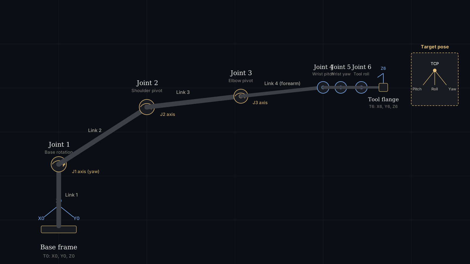
A camera knows where things are in the camera frame. A robot knows where its flange is in the base frame. Hand-eye calibration finds the one rigid transformation that connects those two descriptions, and once you have it, a point detected in an image can be expressed in robot coordinates and reached.
Formally, the problem is written AX = XB, where A and B are the relative motions measured by the robot and by the camera between pairs of poses, and X is the unknown constant transformation between them. OpenCV solves it with cv::calibrateHandEye, which takes arrays of robot gripper-to-base rotations and translations, arrays of target-to-camera rotations and translations from pose estimation, and returns the camera-to-gripper rotation and translation:
Five solver methods are implemented, and the choice is not cosmetic. Three solve rotation first and then translation (separable solutions): Tsai–Lenz, Park–Martin, and Horaud–Dornaika. Two solve rotation and translation simultaneously: Andreff and Daniilidis, the latter using dual quaternions. In practice you should run at least two of them on the same sample set. If they disagree materially, your data is the problem, not the algorithm — and that disagreement is the cheapest diagnostic available in this whole procedure.
Eye-in-hand or eye-to-hand: the choice that determines the whole procedure
Everything downstream depends on where the camera is bolted, and the two configurations are not interchangeable.
- Eye-in-hand. The camera is rigidly attached to the flange or tool and moves with the robot. You solve for the camera-to-flange transform. The calibration target stays fixed in the workspace and its position does not need to be known, but it must not move during the capture. This is the direct form of
calibrateHandEyeand the case most tutorials document. - Eye-to-hand. The camera is fixed to the cell and the target is mounted on the robot. You are solving for the camera-to-base transform. The target’s transform relative to the flange stays constant, and the robot provides the base-to-gripper poses. This is the configuration that most often gets implemented incorrectly, because it is usually better posed as the robot-world/hand-eye problem, which OpenCV solves separately with
cv::calibrateRobotWorldHandEye, returning the base-to-world and gripper-to-camera transforms simultaneously.
Pick the configuration before you print anything. The target goes on the opposite side from the camera in both cases, but the transform you get back and the way you use it are different, and mixing them up produces a calibration that looks numerically fine and positions parts in the wrong place.
If you are still choosing between the two mounting strategies, or comparing camera classes for the cell, our vision system guide covers the eye-in-hand versus eye-to-hand trade-off and camera selection. This article assumes that decision is made.
Prerequisites: intrinsics, a rigid mount and a repeatable TCP
Hand-eye calibration amplifies whatever error is already present in three upstream things. Fix them first or the result is meaningless.
Camera intrinsics. The intrinsic matrix and distortion coefficients must come from a proper cv::calibrateCamera run on your lens at your working distance, with the target filling a good fraction of the frame and appearing near all four corners. Intrinsics are a property of the lens and sensor, not of the scene, and a bad intrinsic calibration cannot be corrected downstream. Do not reuse intrinsics published for a different lens, a different resolution, or a different crop.
A rigid mount. The whole method assumes the camera-to-flange relationship is constant. A bracket that flexes under acceleration, a camera held by a clamp on a tube, or a cable pulling on the housing will produce a calibration that was true for about four seconds. If you can move the camera by hand pressure after mounting, it is not mounted.
A known and repeatable TCP. The robot’s tool centre point definition must be correct, because the poses you record are flange or tool poses in the base frame. Our end effector selection guide covers how the TCP is defined and why an undefined TCP propagates into every downstream coordinate. If the TCP is wrong, the hand-eye result absorbs the error and the system works only at the exact pose where you calibrated it.
Finally, check the frame conventions before you write any code. ROS follows REP 103, where the camera optical frame is right-down-forward and the transform you publish is between defined named frames. Robot controllers report orientation variously as Tait-Bryan XYZ Euler angles, axis-angle, or quaternions, and some report clockwise-positive rotations where the vision library expects counterclockwise. Converting between them incorrectly is one of the most common causes of a hand-eye result that is close but visibly wrong.
Checkpoint 1: the calibration target and the camera intrinsics
Generate the target rather than buying one. OpenCV’s object detection modules include ArUco marker boards and ChArUco boards, and marker-based boards have a practical advantage over a plain chessboard: individual markers are independently identifiable, so the board can be partially occluded or only partly in view and still be resolved. Print at a known scale, measure the printed marker width and separation with calipers, and enter the measured values — not the nominal ones. Printer scaling is off more often than it is right.
Mount the printed pattern on something flat and stiff. A sheet of paper taped to a table bows; a bow of a couple of millimetres across a 200 mm board is a real pose error. Aluminium plate, glass or a flat cast surface is the standard choice, and for eye-to-hand the board should be bolted to the flange with a rigid bracket.
Checkpoint 1 pass criterion: reprojection error from the intrinsic calibration is stable, the board is flat and measured, and the target does not move when the table is bumped.If reprojection error is high or varies frame to frame, fix exposure, focus and lighting before going further. Everything downstream is bounded by this number.
Checkpoint 2: the pose set — rotation diversity is the real requirement
This is where most hand-eye calibrations fail, and it fails silently because the solver still returns a number. The MoveIt 2 hand-eye tutorial is explicit about the two constraints that matter: the calibration can be estimated from a sequence of five or more poses, the result typically improves with a few more samples and plateaus after about twelve to fifteen, and each pair of poses must include some rotation — and not always around the same axis, because at least two rotation axes are needed to uniquely solve the calibration.
Translated into a procedure for a production arm:
- Capture 15 to 25 samples, not five. Five is the mathematical minimum, not a working specification, and it leaves no margin for a bad sample.
- Rotate about at least two, preferably three, axes between consecutive poses, with a meaningful rotation — manufacturer guidance for eye-to-hand procedures commonly recommends end-effector rotations greater than 30°. A pose set that only translates gives a translation-only solution and an undefined or wild rotation.
- Spread the target across the image, including the corners. Corners are where distortion is largest, and a target only ever seen near the centre gives you a calibration that is only valid near the centre.
- Vary the working distance across the range you will actually use, so the depth direction is observable.
- Keep the robot in the same configuration family. Do not let the arm flip wrist configuration between samples unless you intend to calibrate both configurations separately.
- Settle before each capture. Vibration and servo settling show up as blur and corner jitter. Dwell briefly, then trigger.
Checkpoint 2 pass criterion: at least 15 samples, rotation about two or more axes between consecutive poses, target observed across the full image and across a range of distances, and every sample detected on the first attempt.Samples that needed retries are samples where something was marginal. Record why.
Checkpoint 3: recording the sample pairs and solving
Each sample is a pair: the robot’s pose in the base frame at the moment of capture, and the target’s pose in the camera frame from pose estimation. Record both together, timestamped, and record the robot pose from the same instant as the image — not from a moment later, and not from a pose the robot was still moving towards. On a moving system this single synchronisation error can dominate every other error source.
Build the two arrays, run the solver, and run it again with a second method:
Store every sample set you capture, with the raw robot poses and the raw target poses, not just the final transform. If you later have to re-solve with a different method, or exclude an outlier, or answer a question about why the system drifted, the raw data is the only thing that lets you do it without moving the robot again.
Checkpoint 3 pass criterion: at least two solvers agree to within your accuracy budget, and the returned rotation is a proper rotation matrix (determinant +1, orthonormal columns).A returned matrix that is not a valid rotation means a frame convention error, not a bad calibration.
Checkpoint 4: residual checks that separate a good solve from a lucky one
A solver returning a number is not evidence. Validate with residuals before you trust anything.
- Leave-one-out. Re-solve N times, each time omitting one sample, and watch how much the result moves. A result that shifts by more than your accuracy budget when any single sample is removed is not converged — it is being held up by that sample.
- Per-sample consistency. For each sample, predict the target pose in the base frame using the calibration and compare with the prediction from the other samples. Large outliers point at a bad target detection or a mis-synchronised robot pose; remove them and re-solve.
- Rotation before translation. Check the rotation agreement between solvers first. Translation is computed from rotation in the separable methods, so a rotation error will show up as a translation error and mislead you if you look at translation first.
- Sanity-check the magnitude. The translation should be physically plausible: the distance from the flange face to the camera optical centre, in metres. If your camera sits 90 mm in front of the flange and the solver returns 400 mm, the data is wrong, not subtle.
- Watch for degeneracy. Small rotation between poses makes the rotation solution ill-conditioned. If the condition of your pose set is poor, add rotation, not samples.
Checkpoint 5: the verification touch test and the pass criterion
Residuals tell you the calibration is self-consistent. Only a physical test tells you it is correct. The standard test is a touch test: pick a physical point in the workspace, have the vision system compute its position in robot base coordinates using the calibration, command the robot to move a pointed tool to that position, and measure the miss.
Run the touch test at the extremes of the working volume, not only where the target was during calibration — at least five points: near, far, left, right, and one at the maximum reach you intend to use. Record the miss in X, Y and Z at each point. A random scatter within budget means the calibration is good. A consistent offset in one direction means a systematic error, usually the TCP, a frame convention, or a sign error in the rotation conversion.
Set the pass criterion from the application, not from a rule of thumb. If the process needs 0.5 mm placement accuracy, the touch test must pass at 0.5 mm at every test point, and the calibration is not done until it does. MoveIt 2 can export the result as a static transform publisher, which is the right way to make it reproducible in ROS 2 rather than hard-coding a matrix in a node.
Checkpoint 5 pass criterion: touch-test miss within the application budget at every test point across the working volume, with the error pattern recorded and explained.An unexplained but in-tolerance error is a warning. It usually means the margin is smaller than you think.
Example calculation: how a small rotation error becomes a millimetre error
Example calculation — planning arithmetic with stated assumptions, not a measurement from a Robotics Engineering Lab bench.Use your own reach and your own accuracy budget. The method, not the numbers, is the point.
A rotation error in the hand-eye transform produces a positioning error that grows with distance, while a translation error does not. For a small angular error θ at a lever arm r, the displacement is approximately rθ with θ in radians.
Two conclusions follow, and both change how you spend your calibration effort. First, to hold 0.5 mm at a 600 mm reach, the hand-eye rotation must be accurate to roughly 0.05° — under one milliradian. Second, rotation error dominates at distance, so the far corner of your working volume is where the calibration is proved or disproved. That is why the touch test must include the maximum reach.
Is 0.05° achievable? Look at the sensing budget. A machine-vision camera with 3.45 µm pixels behind a 6 mm lens has an angular resolution of roughly arctan(3.45×10⁻⁶ / 6×10⁻³) ≈ 0.033° per pixel. With subpixel corner refinement at about one tenth of a pixel, target feature localisation reaches roughly 0.003°, which is an order of magnitude better than the 0.05° budget — before you account for board flatness, printing scale error, robot repeatability and synchronisation. The sensing chain is not the limiting term in a properly executed calibration; the pose set and the mounting rigidity are.
Eye-to-hand: what changes, and the robot-world form of the problem
For eye-to-hand, the camera is fixed and the target moves with the robot. You can force the problem into the eye-in-hand form by inverting the robot poses and passing base-to-gripper instead of gripper-to-base — this works and is widely done — but the cleaner formulation solves for both unknowns at once. OpenCV provides cv::calibrateRobotWorldHandEye, which takes world-to-camera and base-to-gripper pose arrays and returns the base-to-world and gripper-to-camera transforms, with separable (Shah, using the Kronecker product) and simultaneous (Li) solvers.
The practical differences that catch people out:
- The target must be rigidly and repeatably attached to the flange. Manufacturer guidance is explicit that the target must not shift relative to the flange or fixture during motion, and recommends rigid mounting brackets. A target held by a gripper jaw is a target that moves.
- The transform you publish is camera-to-base, not camera-to-flange. Using it as a flange transform is a classic error.
- The base frame must be the same frame the robot reports poses in. If the robot reports in a user or work-object frame while you assume the base frame, the result absorbs the difference.
- You are also calibrating where the robot is in the world. That is a genuinely useful by-product for multi-robot or robot-plus-conveyor cells, and it is also a new way to be wrong.
Failure diagnosis: the six ways a hand-eye calibration goes wrong
| Symptom | Likely cause | Test that proves it |
|---|---|---|
| Rotation plausible, translation off by a large constant | Target moved during capture, or the frame the camera is mounted to is not the frame you recorded | Re-measure the target position before and after; confirm the flange frame name |
| Translation plausible, rotation wild or non-physical | Insufficient rotation diversity; poses nearly collinear or single-axis | Re-capture with two or more rotation axes and rotations above 30° |
| Result changes materially when you add or remove a sample | Poorly conditioned pose set, or one outlier sample dominating | Leave-one-out re-solve; check per-sample reprojection error |
| Consistent offset in one direction in the touch test | Wrong TCP, or a rotation-convention mismatch (Tait-Bryan vs axis-angle, sign of rotation) | Re-verify the TCP; convert one robot pose by hand and compare |
| Accurate near the calibration poses, poor at the edges | Intrinsics or distortion not modelled across the field; target too small or too far | Re-do intrinsic calibration with the board in the corners; move the target closer |
| Was good, now drifted after a shift | Camera mount compliance or thermal growth; cable tension on the housing | Re-run the touch test cold and warm; load-test the bracket by hand |
If the symptom is a general accuracy or repeatability problem rather than a vision-specific one, the fault may not be in the calibration at all. Robot kinematic error, lost mastering and thermal growth all present the same way, and separating them is a different exercise — see our robot arm calibration guide, which covers mastering, kinematic calibration and the ISO 9283 definitions of accuracy and repeatability.
Indicative 2026 prices for the camera and target
| Item | Relevant specification | Indicative 2026 price (USD) | Source |
|---|---|---|---|
| Intel RealSense D435i depth camera (82635D435IDK5P) | Stereo depth with IMU, USB | $355.00 | DigiKey / Mouser listing |
| Intel RealSense D435 depth camera (82635D435IFMP) | Camera module only | $322.50 | DigiKey listing |
| Teledyne FLIR Blackfly S BFS-U3-31S4M-C | 3.1 MP mono, Sony IMX265, global shutter, 3.45 µm pixels, USB3 Vision, GenICam | $565.00 | Edmund Optics |
| Teledyne FLIR Blackfly S BFS-U3-32S4C-C | Colour variant, 118 fps, USB3 Vision | $1,080.30 | Edmund Optics |
| Calibration target (ArUco or ChArUco board) | Pattern generated by OpenCV’s object detection module, printed and measured | Print and rigid backing only — no verified commercial board price quoted | OpenCV documentation |
The depth-camera route and the industrial 2D route solve different problems. A stereo depth camera gives you range without a separate ranging step and is very effective for close-range bin work and for development, but a global-shutter industrial camera with a fixed focal length lens gives more stable geometry for precise pose estimation, and it is what a production cell will usually end up with. Higher-resolution industrial cameras and lens, lighting and mounting packages are typically configured and quoted by a machine-vision supplier rather than listed at a single price; request a quotation for a production installation. Prices are United States list prices in US dollars; Robotics Engineering Lab did not verify Canadian distributor pricing, so no CAD figure is quoted.
When to recalibrate, and how to keep the result reproducible
A hand-eye calibration is a measurement of a mechanical state, so it expires when that state changes. Recalibrate after any of the following: the camera is removed or remounted; the bracket is touched, repaired or replaced; the lens is changed, refocused or its aperture changed if focus shifts; the camera is bumped or the mount is loaded differently; the tool or flange interface changes; the robot is re-mastered or has significant maintenance on the wrist; or the touch test starts failing. For eye-in-hand on a production cell, put the touch test on a periodic schedule so drift is found by a test rather than by a quality escape.
Make the result reproducible in three ways. Version-control the sample data and the transform together, so any published calibration can be traced to the poses that produced it. Publish the transform as a named static transform in the ROS 2 graph rather than embedding a matrix in a node, and set the frame names deliberately. And record the pass criteria with the result — the touch-test misses, the solver used, the sample count and the date — so the next person knows what the calibration was proved against. Our MoveIt 2 Setup Assistant guide covers the frame and configuration discipline this depends on, and our ros2_control guide covers how the robot state you record during calibration is produced in the first place.
Safety and scope
Hand-eye calibration requires jogging the robot through a set of poses, often near fixtures, with a person initiating motion. That is a hazardous activity. Perform it at reduced speed inside a properly safeguarded cell, under the site’s energy-control and lockout/tagout procedure, with the person initiating motion in control of the enabling device and clear of the swept path. Where the robot shares space with people, the applicable robot safety standard and your site risk assessment govern, not this article. Nothing here is a risk assessment, a certification, or an approval of any cell. Have a qualified integrator or controls engineer review the procedure before it runs in production.
Sources and methodology
The calibrateHandEye and calibrateRobotWorldHandEye interfaces, the five hand-eye solver methods and their source papers, and the robot-world solvers are taken from the official OpenCV calib3d documentation, accessed August 27, 2026. That page is the authoritative source for this article because it documents the exact function signatures, the five hand-eye solver enumerators, the input order for the rotation and translation vectors, and the AX = XB problem statement the method below is built on. The underlying methods are R. Tsai and R. Lenz, “A New Technique for Fully Autonomous and Efficient 3D Robotics Hand/Eye Calibration” (1989); F. Park and B. Martin, “Robot Sensor Calibration: Solving AX = XB on the Euclidean Group” (1994); R. Horaud and F. Dornaika, “Hand-Eye Calibration” (1995); N. Andreff, R. Horaud and B. Espiau, “On-line Hand-Eye Calibration” (1999); and K. Daniilidis, “Hand-Eye Calibration Using Dual Quaternions” (1998), with the robot-world Kronecker-product method from M. Shah (2013). Sample-count guidance, the plateau behaviour after roughly twelve to fifteen samples, the requirement for rotation about at least two axes, the eye-in-hand frame setup and the static-transform export are from the MoveIt 2 hand-eye calibration tutorial published by Picknik for the Humble and Rolling distributions; the right-down-forward camera optical frame that setup assumes is specified in ROS REP 103, accessed August 27, 2026, which is the document to check first whenever a calibration result looks like a frame-convention error rather than a measurement error; verify package status in your own distribution before relying on it. The recommendation for end-effector rotations greater than 30°, capture counts of 10 to 20 images, and rigid target mounting follow published robot-manufacturer developer guidance for eye-in-hand and eye-to-hand procedures. Camera specifications and single-unit prices are from Edmund Optics and DigiKey listings accessed August 27, 2026. The rotation-to-linear-error arithmetic and the angular-resolution estimate were computed from the stated assumptions and the cited pixel size, and every assumption appears in the calculation block. Robotics Engineering Lab has not performed a hand-eye calibration on hardware, has not measured the errors described, and does not sell cameras or calibration hardware. The pass criteria are engineering practice, not a standard.
Frequently asked questions
How many poses do I need for a hand-eye calibration?
The mathematical minimum is small, but it is not a working specification. The MoveIt 2 tutorial states the calibration can be estimated from a sequence of five or more poses, that the result improves with a few more samples and typically plateaus after about twelve to fifteen. Capture fifteen to twenty-five, spread the target across the whole image and across a range of distances, and include rotation about at least two axes between consecutive poses. Five samples leave no margin for one bad detection.
What is the difference between eye-in-hand and eye-to-hand calibration?
In eye-in-hand the camera is rigidly mounted on the flange and moves with the robot, the target stays fixed in the workspace, and you solve for the camera-to-flange transform using cv.calibrateHandEye. In eye-to-hand the camera is fixed to the cell, the target is mounted on the robot, and you solve for the camera-to-base transform, which is better posed as the robot-world problem using cv.calibrateRobotWorldHandEye. The target always goes on the opposite side from the camera, but the transform you get back is different and cannot be used interchangeably.
Why does my hand-eye calibration return a plausible translation but a bad rotation?
Usually because the pose set lacks rotation diversity. If consecutive poses mainly translate, or all rotate about the same axis, the rotation is not uniquely observable and the solver returns whatever fits the noise. The MoveIt documentation is explicit that at least two rotation axes are needed to uniquely solve the calibration. Re-capture with meaningful rotations about two or three axes, with manufacturer guidance commonly recommending end-effector rotations greater than thirty degrees.
How accurate does a hand-eye calibration need to be?
Set the budget from the application, then convert it to a rotation tolerance. A rotation error grows with reach while a translation error does not: at a 600 mm reach, 0.30 degrees gives about 3.1 mm, 0.10 degrees about 1.05 mm, and 0.05 degrees about 0.52 mm. So a 0.5 mm placement requirement at that reach needs the hand-eye rotation accurate to roughly 0.05 degrees. Prove it with a touch test at the extremes of the working volume, not only where the target was during capture.
Can I use a chessboard instead of an ArUco or ChArUco board?
Yes, and OpenCV includes the corner detection and subpixel refinement functions for it. The practical difference is robustness: individual markers on an ArUco or ChArUco board are independently identifiable, so the board can be partially occluded or only partly in view and still be resolved, which happens often on a cluttered robot wrist. Either way, measure the printed marker width and separation with calipers and enter the measured values, because printer scaling is wrong more often than it is right.
How often should I recalibrate a robot camera?
Whenever the mechanical state the calibration measured has changed: the camera is removed or remounted, the bracket is touched or replaced, the lens is changed or refocused, the mount is bumped or loaded differently, the tool or flange interface changes, or the robot is re-mastered or has wrist maintenance. For a production cell, put the touch test on a periodic schedule so drift is detected by a test rather than by a quality escape, and record the touch-test misses alongside every published calibration.