Version note: ROS 2 and MoveIt 2 package APIs evolve. The commands below use the current ROS 2 style and the official MoveIt Setup Assistant workflow. Confirm package names and launch arguments for the distribution installed on your machine before connecting a real arm.
What the Setup Assistant actually creates
The MoveIt 2 Setup Assistant is not a motor driver, a robot controller, or a safety PLC. It is a configuration tool that takes a robot description and helps generate the semantic and planning files MoveIt needs. The result commonly includes an SRDF, kinematics configuration, joint limits, planning pipeline settings, controller mappings, RViz configuration, and launch files. These files tell MoveIt what the robot means and how to plan for it; they do not automatically make an unconfigured hardware interface safe.
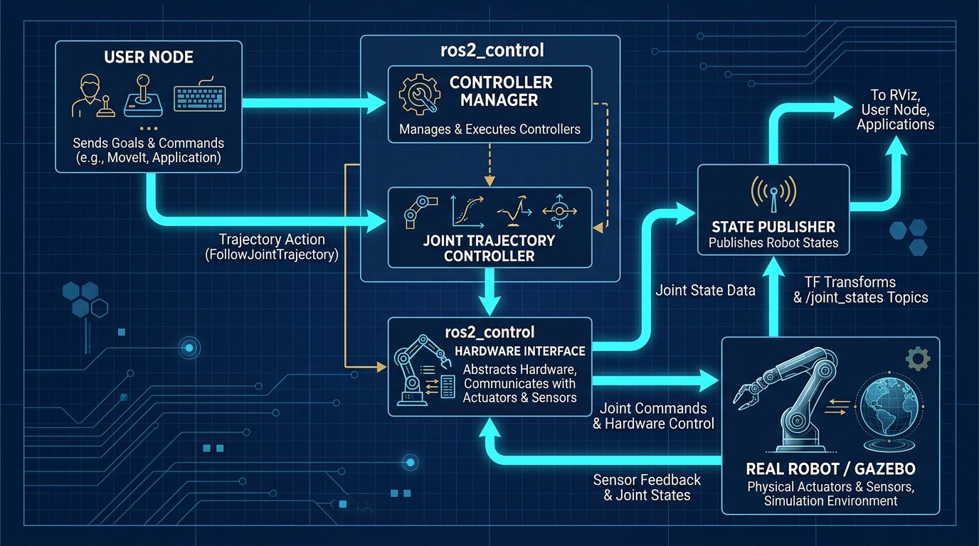
The central separation is worth keeping visible. A URDF or Xacro describes links, joints, geometry, inertial data, and limits. The SRDF adds semantic information such as the arm planning group, gripper group, virtual joint, named poses, end effectors, and disabled self-collision pairs. MoveIt plans a trajectory from that model. `ros2_control` exposes command and state interfaces to controllers. A hardware plugin or vendor driver then communicates with the physical robot.
This separation explains a common failure: the robot appears correctly in RViz, MoveIt produces a green trajectory, and the real arm does not move. The model and planning package may be correct while the controller name, action interface, joint order, or hardware driver is wrong. Treat planning validation and hardware commissioning as separate gates.
Prerequisites: URDF, Xacro, and a clean workspace
Start with a robot description that loads without warnings. The root link, six revolute joints, parent-child order, axis vectors, origin transforms, limits, and visual/collision meshes need to be internally consistent. For a real arm, use the manufacturer’s supported ROS 2 description or a reviewed package. For a custom arm, validate link frames against measured dimensions and the controller’s joint order.
Create or select a ROS 2 workspace that already builds the description package. A typical layout is:
~/robot_ws/src/robot_arm_description/
~/robot_ws/src/robot_arm_bringup/
~/robot_ws/src/robot_arm_moveit_config/
Build the workspace and source it before launching the assistant. The exact dependency command depends on the ROS 2 distribution and operating system; use the official installation instructions for that distribution. The MoveIt documentation starts the assistant with:
ros2 launch moveit_setup_assistant setup_assistant.launch.pyIf the command is not found, do not copy a random package from an old ROS 1 tutorial. Confirm that the MoveIt 2 packages for your ROS 2 distribution are installed, source the correct setup file, and check the official documentation. The Setup Assistant’s UI and generated files have changed across releases.
Step 1 — Load the robot model and inspect frames
Choose Create New MoveIt Configuration Package, then load the URDF or Xacro file. If the description requires Xacro arguments, provide them exactly as the vendor package expects. Wait for the model to render and inspect the link tree before configuring anything else. A missing mesh is mostly a presentation problem; a wrong joint origin or axis changes the kinematics and must be fixed in the description package.
Check units and conventions at this point. Revolute joint positions are expressed in radians in ROS interfaces, while link dimensions are normally in metres. A mesh exported in millimetres but interpreted as metres can make the arm appear enormous and invalidate every collision and reach result. Confirm that the visual and collision meshes have compatible origins and scales.
Checkpoint: the robot should have one connected tree, each actuated joint should have the intended parent and child, and the default pose should not contain impossible joint values. Do not continue by hiding a broken link or accepting a warning you do not understand.
Step 2 — Generate and review the self-collision matrix
The assistant can sample robot configurations and identify link pairs that are never in collision for the tested model. Those pairs can be disabled in the SRDF so the planning scene does not perform unnecessary checks. This improves planning performance, but it is not permission to disable a pair that can collide with a tool, cable, payload, fixture, or a different joint limit configuration.
Review the generated matrix rather than treating it as a final safety analysis. Self-collision geometry must be conservative enough for the model’s accuracy, mesh simplification, and attached tooling. If a mesh is missing or a joint limit is wrong during sampling, the matrix can be misleading. Regenerate it after meaningful model changes and document any manually disabled pair.
MoveIt collision checking also differs from a safety-rated protective system. The planning scene predicts geometry from a model; it does not measure a person in the cell or replace a safety scanner, guard, interlock, or risk assessment. The existing robot safety standards guide explains why a planning scene should not be described as safeguarding.
Step 3 — Define virtual joints and planning groups
A fixed-base six-axis arm commonly uses a fixed virtual joint connecting the robot’s base link to the world frame. A mobile manipulator may need a planar, floating, or other virtual-joint relationship depending on how the base is represented. For a stationary arm, the virtual joint expresses the semantic connection to the world; it does not replace the real mechanical base mounting or the TF configuration used by the application.
Planning groups are the names MoveIt uses for meaningful sets of joints or links. Create an arm group as a kinematic chain from the base link to the tool flange. If the arm has a gripper, create a separate gripper group and, when appropriate, an arm-with-gripper group. Avoid selecting joints by visual order alone. Confirm the chain’s first and last links, joint order, and whether fixed joints are being included as links rather than commanded variables.
Choose a kinematics solver supported by the installed distribution and robot. KDL is a common general-purpose choice. IKFast or another plugin may be appropriate when a verified solver exists for the exact geometry. Pick a search resolution and timeout that match the task; a larger timeout can help a difficult pose but also increases latency. Record the values in version control so a later change is reviewable.
Step 4 — Add named poses and the end effector
Named poses such as home, ready, or stowed are semantic starting points for applications and demonstrations. They are not automatically safe positions. Choose joint values inside the documented limits, verify the pose in RViz, and consider cable twist, singularity proximity, tool clearance, and the cell’s actual guarded space.
When a gripper is represented as a group, label it as an end effector and connect it to the correct parent link. This lets MoveIt reason about attached objects and grasping workflows. Confirm that the parent link is the tool flange or the documented mounting link, not a convenient visual mesh name. If the tool is mechanically offset, represent the transform accurately and configure the controller’s tool data separately.
A useful Example calculation — not a test result is to check the tool transform: if the gripper TCP is 120 mm along the tool Z axis and the mesh origin is 35 mm behind the flange, the model should show a 0.155 m total transform only if those offsets are in the same frame and direction. Do not add distances that are already included in a mesh origin. A wrong TCP can look like a planning failure even when the SRDF is correct.
Step 5 — Configure ros2_control without guessing names
The Setup Assistant can generate or help add controller configuration, but the generated controller name must match the controller manager that actually runs. The ROS 2 joint trajectory controller accepts trajectories with joint names, positions, velocities, accelerations, and timing. The interface and joint order must match the hardware or simulation controller, and the state interfaces must publish feedback at a rate appropriate to the application.
A minimal controller configuration may look like this, but the joint names and interfaces are placeholders that must be replaced:
arm_controller:
  ros__parameters:
    type: joint_trajectory_controller/JointTrajectoryController
    joints:
      - joint_1
      - joint_2
      - joint_3
      - joint_4
      - joint_5
      - joint_6
    command_interfaces:
      - position
    state_interfaces:
      - position
      - velocity
The package generated for MoveIt commonly contains a second mapping that tells MoveIt which controller exposes the `FollowJointTrajectory` action. The name must match the running ROS 2 controller. A mismatch can produce a successful plan followed by an execution error. Inspect the active controller list and action topics rather than changing names until the error disappears.
The official `ros2_control` documentation describes hardware components, command interfaces, and state interfaces. The official joint trajectory controller documentation describes the controller’s expected trajectory and interface behaviour. Use those references for the installed distribution; the site’s ros2_control architecture guide provides broader context but does not replace the distribution documentation.
Step 6 — Generate the package and test in RViz
Generate the configuration package into the workspace’s src directory with a descriptive name such as robot_arm_moveit_config. Inspect the generated files before building. At minimum, review the SRDF, kinematics YAML, joint limits YAML, planning pipeline configuration, controller mapping, RViz configuration, and launch files. Commit the generated package only after removing machine-specific paths and confirming that the maintainer and license metadata are correct for your project.
Build and source again. Launch the generated demo or planning configuration with mock hardware if the package provides it. In RViz, confirm that the planning group is selectable, the start state matches the robot state, the goal marker can be moved, collisions are visualized, and the planned trajectory stays inside joint limits. Move the slider through each trajectory and look for sudden wrist flips, self-collisions, frame jumps, and implausible velocities.
Checkpoint: a valid plan must be reproducible from a clean terminal using documented source commands. If it only works after manually exporting an undeclared path or opening a different workspace, the package is not ready for another engineer or a deployment pipeline.
Step 7 — Connect execution in layers
Do not connect the real arm immediately after RViz planning succeeds. First run with a fake or simulated controller, then with a hardware driver in a restricted mode, and only then perform a controlled motion under the manufacturer’s commissioning procedure. Use the lowest practical speed and acceleration, keep the hazard zone controlled, and verify the emergency stop and protective stop functions independently of MoveIt.
For a real robot, identify the vendor driver’s supported ROS 2 distribution, controller mode, network interface, joint naming, calibration state, and command interface. Some drivers expose a trajectory action; others require a vendor controller or teach-pendant mode before accepting external commands. MoveIt should be the high-level planner, not the only layer deciding whether a machine may move.
Use the robot simulation software comparison when selecting a validation environment. If the path approaches a singularity, inspect the kinematic assumptions in the existing inverse kinematics guide and sample the full trajectory, not only the goal pose. Simulation can identify a bad model or path; it cannot certify the actual cell.
Failure diagnosis by layer
| Symptom | Likely layer | First check |
|---|---|---|
| Model is invisible or huge | URDF/Xacro or mesh | Units, mesh path, root link, and Xacro arguments |
| Planning group is empty | SRDF | Chain endpoints, joint selection, and generated package |
| RViz refuses a goal | Limits, collisions, or kinematics | Joint limits, self-collision matrix, solver, and frames |
| Plan succeeds but execution fails | Controller bridge | Controller name, action interface, joint order, and active controller state |
| Robot moves the wrong joint | Hardware mapping | Joint names, sign conventions, zero offsets, and driver configuration |
| Real arm drifts from RViz | Calibration or model | TCP, base frame, mastering, payload, and measured joint state |
A “successful build” proves only that the package compiled. A “successful plan” proves that the software found a path through its model. A “successful execution” still does not prove that the cell is safe. Keep those claims separate in documentation and in the commissioning checklist.
Version control and reproducibility
Save the ROS 2 distribution, MoveIt version, robot description commit, generated package commit, controller configuration, and launch command in a README next to the package. Record any manually edited Setup Assistant output. If the model is a Xacro file with arguments, document the values used to generate the configuration. A package that depends on an undocumented local path is difficult to maintain and dangerous to hand over.
After changing a mesh, joint limit, tool, controller, or mounting transform, regenerate or review the affected files. A changed collision mesh can invalidate the self-collision matrix. A changed joint order can invalidate both the controller and the SRDF. A changed tool can alter payload, reach, singularity proximity, and collision geometry. Treat the package as an engineering configuration, not a disposable RViz demo.
Sources and methodology
This tutorial follows the official MoveIt Setup Assistant sequence and keeps the planning, description, controller, and safety layers separate. Commands are shown in current ROS 2 syntax, but package names and generated YAML can change between distributions. The examples are configuration illustrations, not a report of a Robotics Engineering Lab hardware test.
- MoveIt 2 Setup Assistant official tutorial — model loading, virtual joints, planning groups, robot poses, end effectors, controllers, and package generation; accessed August 21, 2026.
- ROS 2 control documentation — hardware and interface architecture; accessed August 21, 2026.
- ROS 2 joint trajectory controller documentation — trajectory and interface requirements; accessed August 21, 2026.
- Universal Robots ROS 2: Build the MoveIt config — vendor integration example and controller boundary; accessed August 21, 2026.
- MoveIt 2 Realtime Servo — singularity and collision checking limits; accessed August 21, 2026.
Frequently asked questions
What does the MoveIt 2 Setup Assistant generate?
It helps generate a MoveIt configuration package containing semantic robot data such as an SRDF, planning groups, kinematics and joint-limit settings, controller mappings, RViz configuration, and launch files. It does not replace a hardware driver, safety PLC, risk assessment, or robot manufacturer commissioning procedure.
Which file should I load into the MoveIt 2 Setup Assistant?
Load the URDF or Xacro description that correctly represents the robot’s links, joints, axes, limits, collision geometry, and frame relationships. If the description needs Xacro arguments, use the values documented by the robot package. Do not continue with a model that has unexplained scale, joint, or transform warnings.
Do I need a virtual joint for a fixed-base robot arm?
A fixed virtual joint connecting the robot base link to the world frame is a common semantic configuration for a stationary arm, although the exact setup depends on the application package. It does not replace mechanical anchoring, controller mounting-orientation settings, or the TF tree used by the real cell.
What planning group and IK solver should I choose?
For a six-axis arm, define the arm as a kinematic chain from the base link to the tool flange and choose a solver supported by the installed ROS 2 and MoveIt 2 distribution. KDL is a common general-purpose choice; IKFast or another plugin is appropriate only when it has been generated and validated for the exact robot geometry.
How do I connect a generated MoveIt package to ros2_control?
Match the MoveIt controller mapping to the controller manager that is actually running. Confirm the controller name, joint order, FollowJointTrajectory action interface, command interfaces, and feedback state interfaces. Test with mock or simulated hardware before connecting a real robot.
Why does the robot appear in RViz but refuse to execute?
RViz can display and plan from a model without a working hardware bridge. Check whether the controller is active, whether its name matches the MoveIt mapping, whether the action interface is available, and whether joint names and zero conventions match the driver. Then verify the vendor’s external-control mode and commissioning requirements.