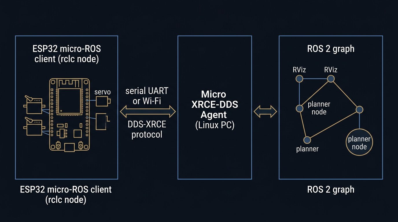
Version note and disclosure: micro-ROS and ROS 2 APIs move between distributions; the workflow below follows the official documentation style, and the firmware is presented as a reference skeleton adapted from the official examples rather than a sketch Robotics Engineering Lab compiled and ran on hardware. Check package names and transport calls for your ROS 2 distribution and library release before connecting motors.
What micro-ROS is, and what it is not
micro-ROS puts real ROS 2 nodes on microcontrollers. The client, written in C and built on the standard ROS 2 client support library (rcl) plus convenience extensions (rclc), gives you nodes, publishers, subscriptions, services, parameters, and lifecycle — the same concepts, and nearly the same tooling, as ROS 2 on Linux. After initialization it can run without dynamic memory allocation, which is the property that makes it usable on the kind of small, deterministic microcontrollers robot arms actually carry. The project documentation, now hosted at micro.vulcanexus.org, describes these seven features — MCU-optimized client API, seamless ROS 2 integration, a resource-constrained middleware, multi-RTOS support, permissive licensing, community ecosystem, and long-term maintainability — as the design contract of the stack.
The equally important statement is what micro-ROS is not. It is not ros2_control on a chip, it is not MoveIt, and it is not a safety system. An ESP32 running micro-ROS is a peer node in the ROS 2 graph — an excellent place for field I/O, joint supervision, and small bench arms, and the wrong place for motion planning or any safety function. Where those boundaries sit is a recurring theme of this tutorial, and our ros2_control guide covers the Linux side of the same boundary in depth.
Licensing is worth one paragraph for anyone building products: the micro-ROS client, middleware, and tools are Apache License 2.0, the same permissive license as ROS 2, per the official license overview. The RTOS you build on top of carries its own terms.
The architecture in one pass: client, agent, DDS-XRCE
Everything in micro-ROS follows from one architectural decision: microcontrollers do not speak full DDS. Instead, the MCU runs a lightweight client that speaks the DDS-XRCE protocol (an OMG standard for "extremely resource-constrained environments") to an agent process on a Linux computer, and the agent speaks ordinary DDS to the rest of ROS 2. The middleware implementation is eProsima Micro XRCE-DDS; its official documentation covers both sides.
- Client (ESP32): your rclc node, static memory pools for streams and messages, and a transport — serial UART, Wi-Fi UDP, Ethernet UDP, or others per the official hardware documentation. No DDS discovery runs on the MCU; the agent owns that.
- Agent (Linux): the Micro XRCE-DDS Agent, typically built from source or installed as a binary. One agent can serve several clients; each client gets a session keyed by an identifier.
- ROS 2 graph: once the session is up, the MCU's topics appear as normal topics.
ros2 node list,ros2 topic echo, and RViz work with no bridging configuration.
This split explains both the strength and the classic failure mode of micro-ROS cells. The strength: tiny MCUs join a ROS 2 system without hogging a Linux computer each. The failure mode: if the agent process stops, the client is alone — so the firmware must hold a safe state on its own, which Checkpoint 3 treats explicitly. On the officially supported hardware list, the classic Espressif ESP32 appears with 520 kB of RAM, 4 MB of flash, FreeRTOS as the RTOS, and UART, Wi-Fi UDP, and Ethernet UDP transports — a comfortable fit for a six-joint arm node.
Hardware and wiring for an ESP32 arm node
The electrical plan for a micro-ROS arm node is the same as for any ESP32 servo controller, and our existing ESP32 controller guide covers it joint by joint. The micro-ROS additions are modest because the ROS 2 link uses interfaces you already have.
- Board: a classic ESP32 dev board is the documented baseline. The Adafruit ESP32-S3-DevKitC-1 lists at 15.95 USD (8 MB flash, no PSRAM) and 19.95 USD (with PSRAM) as of August 25, 2026 — Indicative 2026 price from Adafruit's US store; the S3's extra RAM is useful for larger message arrays, but treat S3 support as community territory and confirm it in the Arduino library release notes for the version you install.
- Servo bus: for a six-axis bench arm, use smart bus servos (Dynamixel or compatible TTL buses) so one UART carries all joint commands and feedback; the bus-wiring rules, termination, and current budgeting in our Arduino Mega wiring guide apply unchanged. If you stay with PWM servos, dedicate an external PWM driver board rather than bit-banging six channels from the ROS callback — see our servo selection guide for the trade-offs.
- Power: one supply rail for logic (5 V to the board's regulator or 3.3 V direct), one for servos, common ground, and no servo current through the ESP32 board. A bench arm with six smart servos can pull several amps at stall — size the supply for stall sum, not idle.
- ROS 2 link: during commissioning, the same USB cable that flashes the board carries the XRCE serial transport. For Wi-Fi later, nothing changes electrically.
Safety plumbing for a bench arm: a physical power switch on the servo rail and a hardware limit (physical hard stops) that does not depend on software. These are educational bench practices, not industrial safeguarding — nothing on this page constitutes a safety approval.
Workstation setup: ROS 2 and the Micro XRCE-DDS Agent
Install ROS 2 using the official distribution docs for your platform (docs.ros.org); pick a supported distribution and use it consistently on both sides of the link. Then build and install the agent from eProsima's repository — the documented sequence is:
git clone https://github.com/eProsima/Micro-XRCE-DDS-Agent.git
cd Micro-XRCE-DDS-Agent
mkdir build && cd build
cmake ..
make
sudo make install
sudo ldconfig      # Linux, so the agent library is found
Run the agent for the serial transport while the board is on USB:
MicroXRCEAgent serial --dev /dev/ttyACM0 -b 115200
# later, for the Wi-Fi transport:
MicroXRCEAgent udp4 --port 8888
The eProsima agent documentation defines these transports and options — including the serial baud default of 115200 — so treat the flags above as the documented interface rather than folklore. On Linux, check your user is in the dialout group if the serial device is permission-denied. Two agent instances can run side by side (one serial, one UDP) while you migrate a project between transports.
Checkpoint 1: firmware that publishes, and the test that proves it
In the Arduino IDE, install the micro-ROS Arduino library release matching your ROS 2 distribution (the library's GitHub repository publishes releases tagged per distribution), select the ESP32 board, and start from the library's publisher example. The reference skeleton below follows that example's structure — it is the pattern to verify against, not a sketch this site compiled on hardware:
#include <micro_ros_arduino.h>
#include <rcl/rcl.h>
#include <rclc/rclc.h>
#include <rclc/executor.h>
#include <std_msgs/msg/int32.h>

rcl_publisher_t publisher;
std_msgs__msg__Int32 msg;

void setup() {
  Serial.begin(115200);
  set_microros_serial_transports();   // XRCE over USB serial

  // node, publisher, executor initialization (rclc)
  // timer-driven publish in loop()
}
The checkpoint is the verification, not the code. With the agent running and the board flashed, prove each layer in order:
- Transport: the agent logs the client session creation. No log, no transport — check the device path, baud, and cable before touching firmware.
- Graph:
ros2 node listshows the board's node (the examples use a name like/micro_ros_arduino_node). - Data:
ros2 topic echoon the example topic shows incrementing values. - Rate:
ros2 topic hzreports the publish period you coded, not something slower — the first sign of buffer starvation appears here.
If all four pass, the client-agent-ROS 2 path is proven, and every later failure is your application code or the physical arm — which is exactly the diagnostic value of the checkpoint.
Checkpoint 2: joint feedback at a fixed rate
The first arm-specific upgrade is a joint-state publisher: read the six servo positions from the bus, timestamp them, and publish. In rclc this means initializing a sensor_msgs/msg/JointState with static storage — pre-allocated name and position arrays sized to six — and publishing from a timer callback at a fixed period rather than from loop() as fast as possible. The rclc executor supports spinning with a period, which gives you a periodic control task in the FreeRTOS environment the ESP32 already runs.
Design decisions that matter more than the code: publish at the rate your consumer needs, not the rate the bus allows; keep joint names identical to your URDF and to the names used on the Linux side (name mismatches are the most common silent failure in joint-state pipelines); and stamp every message, because downstream tools timestamp by header when present. Acceptance for this checkpoint: ros2 topic hz steady at the chosen rate over minutes, joint values in the correct units (radians, if that is what the rest of the system expects), and RViz (with a robot description) showing a stable model.
Checkpoint 3: a command subscriber that moves one servo
Close the loop in the safe direction: commands flow Linux → ESP32, one joint only, small range of motion, arm on blocks. Subscribe to a trajectory- or joint-command topic, and in the callback write one servo goal position and return — no waiting on the bus inside the callback. Acceptance: commanded step, observed motion, published feedback confirms the step, and repeated commands produce repeatable motion.
Then test the failures deliberately, because this is where a bench arm earns trust:
- Agent killed mid-motion: the servo must finish its last command and stop; the firmware keeps its last safe state, and joint-state publishing stops or flags stale.
- Wi-Fi drop (after Checkpoint 4): same expectation. Reconnection should require a session re-establishment, not a silent assumption that data is fresh.
- Garbage command (out-of-range goal): clamped or rejected at the MCU, never forwarded raw to the servo.
This checkpoint set is deliberately hostile. A node that passes it degrades the way a supervision layer should: visibly, and toward rest.
Checkpoint 4: the Wi-Fi transport swap, and what it costs
Switching to Wi-Fi is a firmware configuration change — the library provides Wi-Fi transport setup with the agent's address and port (the examples use UDP port 8888) — plus an agent running in UDP mode. The checkpoint is to re-run Checkpoints 1–3 over the air and compare the numbers you recorded on serial: session establishment time, ros2 topic hz mean and jitter, and any dropped messages over a fixed window.
Expect worse numbers and plan around them. Wi-Fi UDP adds latency and loss; congestion and roaming make it bursty. For telemetry and supervision this is usually irrelevant. For a closed loop that depends on every message arriving, it is a design constraint you measure, not assume — which is why the division-of-labor section below pushes timing-critical control off the Wi-Fi path entirely. Keep the serial transport working as a fallback; it is your commissioning tool every time the network misbehaves.
Memory, rate, and message budgets
Example calculation — planning arithmetic with stated assumptions, not a measurement from our bench.Recompute with your own message sizes and rates before committing a design.
The serial transport budget is simple enough to compute on paper. A 115200 baud 8N1 link moves about 11,520 usable bytes per second. A compact six-joint JointState — header plus six float64 positions, no names — serializes to roughly 60 to 70 bytes, and the XRCE protocol adds framing on top; call it about 90 bytes on the wire per message. That gives a theoretical ceiling near 11,520 / 90 ≈ 128 messages per second, and a practical sustained rate comfortably below it once acknowledgments and session traffic share the stream. A 50 Hz joint-state stream uses under half the link; a 100 Hz stream is marginal at 115200 baud. The fixes are standard: raise the baud rate (the agent flag and the firmware Serial.begin() must match), slim the message, or move to Wi-Fi/Ethernet.
Memory follows the same discipline. The official hardware documentation describes micro-ROS targets as MCUs with "tens of kilobytes" of RAM, and the classic ESP32's 520 kB leaves room for a six-joint node with buffers to spare — but buffers are configured, not free. Reliable stream history depth, MTU, and per-topic queue depth all allocate static pools at initialization; the middleware configuration tutorial in the micro-ROS docs is the authoritative guide to tuning them down. The failure signature of getting it wrong is publishes that silently block or a ros2 topic hz that sags under load — which is why Checkpoint 1 measures rate before anything else.
Division of labor: ESP32 node versus ros2_control on Linux
Where micro-ROS ends and ros2_control begins is the design decision this tutorial keeps circling, so state it plainly. MoveIt, planners, and the trajectory-execution interface live on Linux. ros2_control — with its controller manager, hardware interfaces, and real-time control loop — also lives on Linux, as our MoveIt 2 configuration tutorial shows from the planning side. The ESP32 micro-ROS node is a peer contributor: joint states up, joint commands down, plus whatever field I/O you give it.
| Function | ESP32 micro-ROS node | Linux ROS 2 computer |
|---|---|---|
| Joint state publishing | Yes — bus reads, timestamps, publishes | Consumes; provides TF and robot state |
| Motion planning | No | MoveIt 2 or custom planners |
| Trajectory execution and interpolation | Optionally final goal positions only | Controller manager, FollowJointTrajectory |
| Field I/O, grippers, sensors | Yes — natural fit | Consumes and sequences |
| Safety functions | Hardware e-stop wiring and hard limits only | Not here either — safety belongs on safety-rated hardware in industrial cells |
Typical reader question: “Why not just publish ROS 2 serial strings from the ESP32 and parse them on the PC?”Answered from the architecture, not from a benchmark we ran.
You can, and for one fixed message it works — until you add a second message type, a second device, or a field robot. micro-ROS gives you typed topics, QoS, timestamps, discovery, and the standard tools for the same effort: ros2 topic echo just works, RViz just works, and the message contract between MCU and PC is a defined IDL instead of a parser. The cost is the agent process and a stricter build setup. Our advice for readers who already maintain serial-parser firmware: try micro-ROS on one node, measure your Checkpoint 1–4 results, and let the numbers decide.
Scope and safety limits
This tutorial describes a hobby- and education-class setup: an ESP32, bus servos, and open-source middleware, none of which are safety-rated. Keep it that way in writing and in practice. Bench arms should have a reachable power switch, hard mechanical stops, and no humans or fingers inside the motion envelope while testing commands from a network — Wi-Fi-latent command delivery is a real hazard on any arm with enough torque to matter. Do not extend this architecture to industrial duty: industrial robot cells keep safety functions on safety-rated hardware and motion authority in the robot controller, under the risk assessment and integration requirements of ANSI/RIA R15.06 in the USA, CSA Z434 in Canada, and ISO 10218-2 for the integrated system. If your project is heading that way, our the North American robot safety standards guide on this site is the right next read.
Sources and methodology
Architecture, features, licensing, hardware capabilities, and transport statements follow the official micro-ROS documentation (now at micro.vulcanexus.org; the former micro.ros.org site redirects there), accessed August 25, 2026: the features and architecture page, the supported-hardware page listing the ESP32 (520 kB RAM, FreeRTOS, UART/Wi-Fi UDP/Ethernet UDP transports), and the linked memory-tuning tutorial. Agent build steps and transport options follow the eProsima Micro XRCE-DDS documentation and its GitHub repository. ROS 2 installation references docs.ros.org. The board prices are Adafruit US listings accessed August 25, 2026, labelled as indicative. The firmware skeleton is adapted from the official micro-ROS Arduino example pattern and presented as a reference to verify, not as a compiled and executed program; Robotics Engineering Lab did not run this tutorial on hardware before publication.
What is micro-ROS used for on a robot arm?
Micro-ROS runs real ROS 2 nodes on a microcontroller, so an ESP32 can publish joint states, subscribe to joint commands, and appear in ros2 node list like any Linux node. Typical arm uses are sensor aggregation, low-level joint supervision, small mobile or bench arms, and bridging bus servos into a ROS 2 system without dedicating a Linux computer to each microcontroller.
Does micro-ROS need the agent program running?
Yes. The microcontroller runs only the client; a Micro XRCE-DDS Agent process on a Linux computer translates the DDS-XRCE protocol into the full DDS data space used by ROS 2. If the agent stops, the client loses its ROS 2 connectivity, so design the arm to hold its last safe state and keep local interlocks working when the agent is down.
Can an ESP32 run MoveIt 2 or ros2_control?
No. MoveIt 2 and ros2_control are Linux-framework components; micro-ROS does not port them to the microcontroller. The ESP32 node is a peer ROS 2 node that publishes and subscribes. Keep planning on a Linux computer, and put real-time hardware management in ros2_control or the vendor driver, as our ros2_control guide explains. The ESP32 is best at field IO, supervision, and small arms.
Should I use serial or Wi-Fi transport for micro-ROS?
Use serial USB for commissioning: it is deterministic, needs no network, and isolates faults. Switch to Wi-Fi UDP when the arm must move untethered, and accept jitter, packet loss, and reconnection logic as part of the design. For closed-loop control at 100 Hz over Wi-Fi, verify delivery statistics on your own network before trusting the loop; many bench arms stay on a cable for exactly this reason.
How much RAM does micro-ROS need on an ESP32?
The micro-ROS documentation describes the target as microcontrollers with tens of kilobytes of RAM, and the classic ESP32 offers 520 kB of SRAM, so the stack fits with room for application code. The practical cost is stream buffers: reliable streams, message history depth, and transport MTU sizes allocate static memory pools. Tune history depth and MTU with the official middleware configuration guide rather than increasing buffers blindly.
Is micro-ROS suitable for industrial robot control?
Not as a safety or motion-authority layer. Micro-ROS is a communication stack, with no safety rating and no guarantee of timely delivery over Wi-Fi. Industrial cells keep safety functions on safety-rated hardware and motion authority in the robot controller or a real-time industrial control system. An ESP32 micro-ROS node can supervise and report, but a work cell must fail safely without it.