
Editorial Disclosure & Scope Notice
This technical sizing guide is an independent engineering analysis based on published mechanical gearing standards (AGMA / ISO 6336) and official manufacturer documentation (Nabtesco, Spinea, Sumitomo Drive Technologies). Robotics Engineering Lab did not destructively test the gearboxes analyzed below. Sizing heavy mechanical speed reducers for multi-axis industrial robots requires rigorous structural simulation of peak emergency stop moments and dynamic payload inertia using our joint torque and reflected inertia calculations. Always consult certified mechanical engineering data and manufacturer application engineers prior to final production release.
Cycloidal Drive Robot Arm Applications: Heavy Joint Demands
In a 6-degree-of-freedom (6-DOF) articulated industrial manipulator, the mechanical speed reducer is the single most load-critical component in the entire drivetrain. While wrist joints (Joints 4, 5, and 6) prioritize ultra-low mass and compact outer diameters, the primary positioning axes — the base waist (Joint 1), shoulder (Joint 2), and elbow (Joint 3) — are subjected to extreme cantilevered gravitational torques, massive dynamic acceleration moments, and severe emergency stop shock loads.
For decades, roboticists building lightweight manipulators frequently specified strain wave harmonic drives across all six axes due to their near-zero backlash, compact coaxial geometry, and large central through-holes. However, when applied to high-payload base and shoulder joints (> 10 kg payload), harmonic drives suffer a fatal vulnerability: the flexible steel cup (flexspline) has very limited fatigue limits and low torsional stiffness under shock loads. An unexpected emergency stop at full arm extension generates a dynamic inertial spike that can shear flexspline teeth or cause catastrophic cup fatigue fracture.
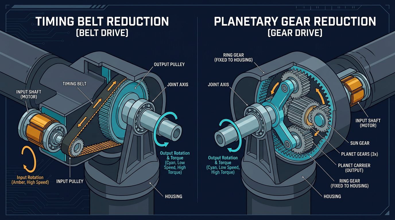
To withstand these severe dynamic forces without sacrificing positioning precision, industrial robot manufacturers (including FANUC, ABB, KUKA, Yaskawa, and Kawasaki) exclusively utilize cycloidal speed reducers (also known as pinwheel reducers, RV reducers, or Spinea TwinSpin drives) in Joints 1, 2, and 3. A cycloidal drive robot arm joint delivers unmatched shock overload resistance (withstanding momentary shock peaks up to 500% of nominal rated torque), exceptional torsional rigidity ($K_T > 100\text{ Nm/arcmin}$), and integrated heavy-duty cross-roller bearings capable of directly absorbing massive overturning moments without secondary external bearing supports, contrasting with conventional timing belts and planetary gearboxes.
Operating Principle and Kinematics of Cycloidal Gearing
A cycloidal drive transforms high-speed motor rotation into high-torque, low-speed output through the rolling interaction of an epitrochoid-profile disc against stationary ring pins:
The Kinematic Architecture
A precision robotic cycloidal reducer consists of four core mechanical sub-assemblies:
- High-Speed Input Shaft with Dual Eccentric Cams: The servo motor couples directly to the input shaft, which features two eccentric cam lobes machined $180^\circ$ out of phase with an eccentricity $e$ (typically $1.0\text{ mm}$ to $3.5\text{ mm}$).
- Dual Cycloid Discs: Two identical tool-steel discs with perimeter cycloidal lobes are mounted onto needle roller bearings on the eccentric cams. The dual-disc configuration balances rotating centrifugal forces dynamically, eliminating high-speed vibration.
- Stationary Ring Pin Housing (Stator): The outer housing holds $N_p$ precision ground cylindrical pins (or roller sleeves) arranged in a pitch circle of radius $R_p$. The number of lobes on each cycloid disc is $N_g = N_p - 1$.
- Output Shaft & Carrier Pins: A rigid output flange contains $N_c$ heavy cylindrical drive pins (fitted with low-friction sliding or needle roller bushings) that pass through oversized circular drive holes machined into the cycloid discs. The diameter of the disc holes equals the carrier pin diameter plus twice the eccentricity ($D_{\text{hole}} = D_{\text{pin}} + 2e$).
Kinematic Reduction Ratio Derivation
For every full $360^\circ$ revolution of the eccentric input shaft, the cycloid disc is driven through one eccentric orbit. Because the disc has $N_g = N_p - 1$ lobes interacting with $N_p$ stationary pins, the disc advances by exactly one lobe in the opposite direction of the input shaft. The single-stage cycloidal reduction ratio $R$ is strictly governed by the lobe count:
$$R = \frac{N_g}{N_p - N_g} = \frac{N_p - 1}{N_p - (N_p - 1)} = N_p - 1 = N_g$$In modern industrial RV-type reducers (such as Nabtesco RV-E / RV-N series), a primary spur gear stage ($i_1$) precedes the cycloidal stage ($i_2$), yielding total single-housing reduction ratios from $i_{\text{total}} = i_1 \times i_2 = 30{:}1$ up to $300{:}1$ in an exceptionally compact axial length.
Constraint 1: Peak Torque, Emergency Stop Moments & Shock Factor
The primary engineering constraint when sizing a cycloidal drive for a robot joint is ensuring the reducer withstands dynamic peak torque $T_{\text{peak}}$ and emergency stop shock torque $T_{\text{E-stop}}$ without exceeding the manufacturer's momentary peak limit $T_{\text{max}}$.
Multi-Tooth Load Sharing Mechanism
In standard involute spur or planetary gears, the entire transmitted load is concentrated across one or two tooth pairs under sliding contact, making them vulnerable to tooth root bending fatigue. In a cycloidal drive, the rolling disc lobes engage 30% to 50% of the ring pins simultaneously under pure compressive rolling contact. This distributes contact stress across multiple hardened surfaces, allowing cycloidal reducers to safely absorb momentary shock loads up to 500% of their rated nominal torque ($T_{\text{momentary}} = 5 \times T_{\text{rated}}$).
The Shock Load Sizing Equation
When selecting a reducer, compute the required maximum torque rating $T_{\text{req}}$ using the application shock factor $K_s$:
$$T_{\text{req}} \ge \left( T_{\text{gravity\_max}} + T_{\text{accel\_max}} \right) \times K_s$$
Where:
• $T_{\text{gravity\_max}}$ — maximum static gravitational moment at maximum horizontal arm reach.
• $T_{\text{accel\_max}} = J_{\text{total}} \times \alpha_{\text{joint}}$ — dynamic acceleration
torque from joint reflected inertia.
• $K_s$ — operational shock factor:
$1.5$ for smooth palletizing,
$2.0$ for high-speed pick-and-place, and
$2.5$ for heavy CNC machine loading or stamping press transfers.
Constraint 2: Torsional Rigidity, Lost Motion & Backlash
In precision robotics, positional repeatability at the Tool Center Point depends directly on the torsional stiffness ($K_T$) and lost motion of each joint reducer. When the robot changes direction or accelerates rapidly, joint elasticity causes angular deflection, resulting in TCP overshoot, path tracking errors, and settling time delays.
Lost Motion vs. True Backlash
Unlike standard gearboxes, precision cycloidal drives exhibit zero geometric backlash because the cycloidal lobes and ring pins are manufactured with tight tolerances and negative clearances (radial preloading). Instead, manufacturers specify Lost Motion:
Definition of Lost Motion
Lost Motion is the total angular displacement measured at the output flange when the output shaft is loaded in both directions to ±3% of rated output torque ($\pm T_{\text{rated}} \times 0.03$). In high-grade industrial cycloidal drives, lost motion is strictly guaranteed to be $< 1.0\text{ arcminute}$ (typically $0.4$ to $0.8\text{ arcmin}$).
Torsional Spring Constant ($K_T$) and TCP Deflection
The elastic torque-deflection curve of a cycloidal drive is non-linear, divided into three distinct stiffness regions:
- Low-Torque Region ($0$ to $0.5 \times T_{\text{rated}}$): Spring constant $K_1 \approx 60\text{ to } 90\text{ Nm/arcmin}$.
- Mid-Torque Region ($0.5 \times T_{\text{rated}}$ to $1.0 \times T_{\text{rated}}$): Spring constant $K_2 \approx 100\text{ to } 160\text{ Nm/arcmin}$.
- High-Torque Region ($> 1.0 \times T_{\text{rated}}$): Spring constant $K_3 \approx 150\text{ to } 220\text{ Nm/arcmin}$.
The angular deflection $\theta_{\text{def}} = T / K_T$ creates a physical linear deflection at the robot end effector of $\Delta x_{\text{TCP}} = L_{\text{reach}} \times \sin(\theta_{\text{def}})$. For a $1.5\text{ m}$ reach arm with a $300\text{ Nm}$ dynamic torque load and $K_T = 120\text{ Nm/arcmin}$:
$$\theta_{\text{def}} = \frac{300\text{ Nm}}{120\text{ Nm/arcmin}} = 2.5\text{ arcmin} = 0.000727\text{ rad}$$ $$\Delta x_{\text{TCP}} = 1500\text{ mm} \times 0.000727 = \mathbf{1.09\text{ mm}}$$This shows why high torsional stiffness in base and shoulder joints is essential for maintaining sub-millimeter precision under dynamic loads.
Constraint 3: Integrated Cross-Roller Bearing Capacities
A major design advantage of modern cycloidal speed reducers is the integration of an internal high-capacity cross-roller output bearing (or paired angular contact ball bearings) directly inside the reducer housing. This allows the reducer to act as the primary structural joint bearing, eliminating external pivot shafts and secondary pillow blocks.
Overturning Moment & Equivalent Load Calculation
Robot joints 1 and 2 experience massive tilting (overturning) moments $M_t$ caused by the cantilevered mass of the entire upper arm and payload. The integrated bearing must support simultaneous radial forces $F_r$, axial thrust $F_a$, and tilting moment $M_t$:
$$M_t = F_r \times L_{\text{moment\_arm}} + F_a \times R_{\text{thrust\_radius}}$$The equivalent dynamic radial load $P_c$ acting on the integrated cross-roller bearing is calculated according to ISO 281:
$$P_c = X \cdot F_r + Y \cdot \left( \frac{2 M_t}{d_{\text{pitch}}} + F_a \right)$$Where $d_{\text{pitch}}$ is the bearing pitch circle diameter, and $X, Y$ are radial/axial dynamic load factors. The nominal $L_{10}$ bearing fatigue service life in operating hours is given by:
$$L_{10h} = \frac{10^6}{60 \cdot n_{\text{avg}}} \left( \frac{C_{\text{dyn}}}{P_c \cdot f_w} \right)^{10/3}$$Where $C_{\text{dyn}}$ is the basic dynamic load rating (in kN), $n_{\text{avg}}$ is the mean output speed (RPM), and $f_w$ is the service load factor (typically $1.2$ to $1.5$ for industrial robotics). Industrial robot specifications require $L_{10h} \ge \mathbf{20{,}000\text{ hours}}$ of continuous production life.
Constraint 4: Input Speed, Thermal Equilibrium & Lubrication
While cycloidal reducers excel in torque density, high input rotational speeds generate significant frictional heat through rolling and sliding contact between the eccentric cam bearings, disc lobes, and carrier bushings. Operating temperature directly influences lubricant film breakdown, seal life, and thermal growth.
Thermal Dissipation & Maximum Continuous Input Speed
Modern brushless AC servo motors operate at rated speeds of 3,000 to 6,000 RPM. However, large cycloidal reducers (such as size 80E or 160E) have maximum continuous input speed ratings of 1,500 to 2,500 RPM due to thermal dissipation limits in enclosed aluminum/steel robot link castings. The continuous input power loss $P_{\text{loss}} = T_{\text{in}} \cdot \omega_{\text{in}} \cdot (1 - \eta)$ converts directly into heat. At 90% mechanical efficiency, a 3 kW drive dissipates 300 W of thermal energy inside the joint casting.
Lubrication Selection: Synthetic Semi-Fluid Grease
Precision cycloidal reducers must be lubricated with specialized NLGI 00 or NLGI 0 synthetic extreme-pressure (EP) semi-fluid grease (such as Nabtesco Molywhite RE No. 00, Harmonic Drive 4B No. 2, or Castrol Tribol GR). Never use standard stiff automotive grease (NLGI grade 2). Heavy grease cannot flow into the tight 5 µm clearances of the eccentric needle bearings, resulting in dry contact, severe frictional overheating, and rapid pin galling within hundreds of operating hours.
Constraint 5: Joint Packaging, Hollow Bore & Cable Routing
When selecting a cycloidal reducer for an articulated robot, mechanical packaging and cable management must be considered early in the structural design:
- Solid-Shaft Reducers (Nabtesco RV-E / Sumitomo F2C): Most compact outer diameter and highest torque density. However, because the center of the reducer is occupied by the eccentric input shaft, all motor power leads, encoder feedback lines, pneumatic air hoses, and EtherCAT network cables must be routed externally around the joint casting via flexible energy chains or slip rings.
- Hollow-Shaft Reducers (Nabtesco RV-C / RV-N / Spinea TwinSpin): Features a large central through-hole (ranging from 25 mm to 100 mm diameter) passing directly through the center of the gearbox. This allows internal routing of all electrical and pneumatic lines through the neutral axis of the robot arm, protecting cables from welding slag, coolant spray, and mechanical snagging, as detailed in our guide to robot base mounting and reaction forces.
Worked Engineering Calculation: Sizing Shoulder Joint (J2) of a 15 kg Payload Robot
Illustrative Sizing Calculation: 15 kg Payload Industrial Robot Arm
Design Requirements: Size the cycloidal speed reducer for Joint 2 (Shoulder) of a 6-axis articulated industrial robot performing heavy CNC machine loading.
System Parameters:
• Maximum horizontal reach from Joint 2 axis to TCP: $L_{\text{arm}} = 1.40\text{ m}$ ($55.1\text{ in}$).
• Rated Payload mass (part + pneumatic gripper): $m_{\text{payload}} = 15.0\text{ kg}$.
• Upper arm link + wrist assembly mass: $m_{\text{link}} = 24.0\text{ kg}$ (center of mass located at $L_{\text{CG}} = 0.65\text{ m}$ from J2).
• Maximum joint angular velocity: $\omega_{\text{max}} = 150^\circ/\text{s} = 2.618\text{ rad/s}$ ($25.0\text{ RPM}$).
• Acceleration time to max speed: $t_{\text{acc}} = 0.25\text{ s}$ → Angular acceleration $\alpha = 2.618 / 0.25 = 10.47\text{ rad/s}^2$.
• Application shock factor: $K_s = 1.50$ (smooth machine tending).
Step 1: Maximum Static Gravitational Torque ($T_g$) $$T_g = \left( m_{\text{payload}} \times g \times L_{\text{arm}} \right) + \left( m_{\text{link}} \times g \times L_{\text{CG}} \right)$$ $$T_g = (15.0 \times 9.81 \times 1.40) + (24.0 \times 9.81 \times 0.65) = 206.01 + 153.04 = \mathbf{359.05\text{ Nm}}$$
Step 2: Rotational Inertia ($J_{\text{total}}$) & Acceleration Torque ($T_a$) $$J_{\text{payload}} = 15.0 \times (1.40)^2 = 29.40\text{ kg·m}^2$$ $$J_{\text{link}} = 24.0 \times (0.65)^2 + 1.20 = 11.34\text{ kg·m}^2$$ $$J_{\text{total}} = 29.40 + 11.34 = 40.74\text{ kg·m}^2$$ $$T_a = 40.74 \times 10.47 = \mathbf{426.55\text{ Nm}}$$
Step 3: Peak Dynamic Torque & Shock Factor $$T_{\text{peak}} = 359.05 + 426.55 = 785.60\text{ Nm}$$ $$T_{\text{req\_max}} = 785.60 \times 1.50 = \mathbf{1{,}178.40\text{ Nm}}$$
Step 4: Reducer Selection — Nabtesco RV-80E
• Rated Nominal Output Torque: $784\text{ Nm}$
• Acceleration Peak Torque: $1{,}568\text{ Nm}$
• Momentary Emergency Stop Torque: $3{,}920\text{ Nm}$
• Torsional Rigidity: $147\text{ Nm/arcmin}$
• Lost Motion: $< 1.0\text{ arcmin}$
• Maximum Overturning Moment: $2{,}940\text{ Nm}$
Step 5: Margin Assessment
• Peak dynamic acceleration ($785.6\text{ Nm}$) is 50.1% of the acceleration limit ($1{,}568\text{ Nm}$).
• Shock-factored requirement ($1{,}178.4\text{ Nm}$) gives a 3.32× safety margin against the emergency stop limit ($3{,}920\text{ Nm}$).
• Static tip deflection: $\theta = 359.05 / 147 = 2.44\text{ arcmin}$ → $\Delta x = 1400 \times \sin(2.44') = \mathbf{0.99\text{ mm}}$.
Comprehensive Decision Matrix: Cycloidal vs. Harmonic vs. Planetary
The table below provides an evidence-based comparison across the three primary speed reducer technologies used in modern robotic manipulator joints:
| Engineering Metric | Precision Cycloidal Reducer | Strain Wave Harmonic Drive | Multi-Stage Precision Planetary |
|---|---|---|---|
| Primary Joint Application | Joints 1, 2, 3 (Base, Shoulder, Elbow) | Joints 4, 5, 6 (Wrist Pitch, Yaw, Roll) | Linear 7th Axis / AGV Wheel Drives |
| Reduction Ratio Range | 30:1 to 300:1 (Single/Dual Stage) | 30:1 to 160:1 (Single Stage) | 3:1 to 100:1 (1 to 3 Stages) |
| Backlash / Lost Motion | < 1.0 arcmin (Zero true backlash) | < 0.5 arcmin (Zero backlash) | 1.0 to 3.0 arcmin (Low backlash) |
| Shock Overload Capacity | 400% to 500% of rated torque | 200% to 250% (Flexspline failure risk) | 200% to 300% (Tooth shear risk) |
| Torsional Rigidity ($K_T$) | 100 to 300 Nm/arcmin (High) | 20 to 60 Nm/arcmin (Moderate/Low) | 50 to 120 Nm/arcmin (Moderate) |
| Tilting Moment Bearing Life | Integrated heavy cross-roller (>20k hrs) | Integrated light cross-roller | Requires external pivot bearings |
| Torque Density (Nm/kg) | 100 to 180 Nm/kg | 150 to 250 Nm/kg (Highest) | 60 to 110 Nm/kg |
| Mechanical Efficiency | 85% to 92% | 75% to 88% | 90% to 97% (Highest) |
| Indicative 2026 Price per Axis | $850 – $2,400 USD | $650 – $1,850 USD | $350 – $950 USD |
Indicative 2026 Prices & Lead Times for Robotic Cycloidal Reducers
Precision cycloidal speed reducers are high-precision mechanical components manufactured from vacuum-degassed bearing steel with sub-micron CNC grinding. All prices below represent indicative 2026 prices in USD (with CAD reference conversions) compiled from public distributor catalogs and manufacturer quotation guidelines (Nabtesco, Spinea, Sumitomo, OnRobot) as of August 2026. OEM volume pricing varies by annual production volume and frame customization.
| Manufacturer & Model Series | Frame Size / Rated Torque | Mechanical Architecture | Indicative 2026 Price (USD) | Indicative 2026 Price (CAD) | Typical Production Lead Time |
|---|---|---|---|---|---|
| Nabtesco RV-E Series | RV-20E ($196\text{ Nm}$ Rated) | Solid shaft, integrated cross-roller | $820 – $1,150 | $1,100 – $1,550 | 4 to 8 weeks (Stock to build) |
| Nabtesco RV-N Series | RV-80N ($784\text{ Nm}$ Rated) | Ultra-compact solid, 30% lighter | $1,450 – $1,980 | $1,950 – $2,680 | 6 to 10 weeks |
| Nabtesco RV-C Series | RV-42C ($412\text{ Nm}$, 45 mm bore) | Hollow through-bore for cable routing | $1,650 – $2,350 | $2,220 – $3,180 | 8 to 12 weeks |
| Spinea TwinSpin TS Series | TS140 ($520\text{ Nm}$ Rated) | High-rigidity cycloidal reducer | $1,380 – $1,890 | $1,860 – $2,550 | 6 to 10 weeks |
| Sumitomo Fine Cyclo F2C | F2C-A35 ($343\text{ Nm}$ Rated) | Zero-backlash robotic gearbox | $950 – $1,420 | $1,280 – $1,920 | 4 to 8 weeks |
| Open-Source / Maker CNC Kits | NEMA 23/34 cycloidal kits | Machined 7075 aluminum / 52100 steel | $180 – $340 | $245 – $460 | 1 to 3 weeks (In stock) |
Typical Reader Question: Can 3D-Printed Cycloidal Drives Work for Real Robot Arms?
Typical Reader Question
"Can I 3D-print a cycloidal reducer using PETG or Nylon on my desktop 3D printer for a functional 6-axis robot arm project?"
Engineering Analysis: 3D-printed cycloidal drives made from PLA, PETG, or carbon-fiber reinforced nylon (PA-CF) can function effectively for educational desktop demonstrators and lightweight hobby arms carrying under 500 g payload. However, polymer materials present four insurmountable physical limitations in functional robotic applications, as explored in our guide to 3D printed robotic arm joints:
- Viscoelastic Creep Under Static Gravity: When the arm holds a horizontal pose, sustained contact pressure causes polymer cycloid lobes to creep (plastically deform) over time, resulting in lost motion that increases from 5 arcmin to over 30 arcmin within weeks.
- Thermal Softening: The glass transition temperature ($T_g$) of PLA is $60^\circ\text{C}$ and PETG is $80^\circ\text{C}$. High-speed motor rotation generates sufficient friction in the eccentric needle bearings to soften the printed cam within 15 minutes of continuous cycling.
- Manufacturing Tolerances: Industrial steel reducers maintain pin-to-lobe clearances under 5 µm ($0.0002\text{ in}$). FDM 3D printers have dimensional tolerances of ±100 to 200 µm, requiring large clearances that introduce 10 to 20 arcminutes of mechanical backlash.
Machining Tolerances & Preventive Maintenance Protocol
For custom robotic joint manufacturing, cycloidal disc profiles must be machined using CNC Wire Electrical Discharge Machining (EDM) or specialized profile grinding. The critical manufacturing tolerances include:
- Disc Profile Tolerance: Profile form tolerance within ± 0.005 mm (5 µm) with surface finish $R_a \le 0.4\text{ μm}$.
- Material Specification: Disc core and ring pins machined from high-purity vacuum-degassed AISI 52100 (100Cr6) bearing steel or AISI 4340 alloy steel, case-hardened to HRC 58–62 with effective case depth $\ge 1.2\text{ mm}$.
- Shaft & Housing Fits: Input eccentric shaft bearing seats ground to ISO k5 / m5; outer pin housing bored to ISO H6.
Preventive Maintenance & Grease Replacement Schedule
To ensure the target 20,000-hour operational lifespan, maintain the following servicing intervals:
- Initial Run-In Inspection (500 operating hours): Measure operating surface temperature; check input/output shaft oil seals for synthetic grease seepage.
- Routine Grease Sampling (Every 5,000 operating hours / Annually): Extract a 5 ml grease sample from the drain port. Analyze for iron particulate concentration ($> 500\text{ ppm}$ indicates abnormal disc wear) and oil separation.
- Complete Lubricant Flush & Refill (Every 10,000 to 20,000 operating hours): Flush old grease using low-viscosity synthetic flushing oil and recharge with certified NLGI 00 synthetic grease to the manufacturer's specified volume fill ratio (typically 70% to 80% internal cavity fill to allow for thermal expansion).
Functional Safety & Motor Holding Brake Integration
When integrating cycloidal gearboxes on vertical robot axes, functional safety under ISO 10218-1/2 and ISO 13849-1 requires careful placement of the joint holding brake:
Because precision cycloidal reducers have high mechanical backdriving efficiency (85% to 92%), cutting power to the arm will cause gravity-induced joint backdriving. A certified spring-applied electromagnetic holding brake must be incorporated. Mounting the brake on the motor input shaft (pre-gearbox) allows a compact brake size because brake holding torque is multiplied by the gear reduction ratio $R$: $$T_{\text{brake\_req}} = \frac{T_{\text{gravity}}}{R \cdot \eta}$$
Safety Warning: Pre-gearbox brakes rely on the mechanical integrity of the gearbox. For critical human-collaborative cells or heavy industrial gantries over operating personnel, conduct a risk assessment under ISO 13849-1 to determine whether a secondary redundant output holding brake is required to safeguard against gearbox mechanical failure.
Sources and Methodology
This technical sizing guide was developed through analysis of published mechanical engineering gear literature and official manufacturer technical manuals, accessed August 2026:
- Manufacturer Technical Manuals: Nabtesco Corporation (Precision Reduction Gear RV Series Design Manual, RV-E/RV-N/RV-C Engineering Catalogs), Spinea s.r.o. (TwinSpin High Precision Reduction Gears Technical Guide), and Sumitomo Heavy Industries (Fine Cyclo Zero-Backlash Speed Reducers).
- Gearing Standards: AGMA 6001-E08 (Design and Selection of Components for Enclosed Gear Drives) and ISO 6336 (Calculation of load capacity of spur and helical gears — surface durability and scuffing).
- Bearing Life Standards: ISO 281 (Rolling bearings — Dynamic load ratings and rating life) and ISO 76 (Rolling bearings — Static load ratings).
- Academic Literature: Kinematic and Dynamic Analysis of Cycloid Speed Reducers (Sensinger & Lipsey, IEEE Transactions on Robotics) and Design Optimization of Cycloidal Drives for Robotic Manipulators.
Frequently Asked Questions
Why are cycloidal drives preferred over harmonic drives for base and shoulder robot joints?
Cycloidal drives share transmitted loads across 30 to 50 percent of their ring pins simultaneously under pure rolling contact, providing momentary shock overload ratings up to 500 percent of nominal torque without permanent damage. In contrast, strain-wave harmonic drives rely on thin, flexible steel flexsplines that suffer tooth shearing or fatigue rupture under heavy dynamic emergency stops and high overturning moments characteristic of Joint 1, Joint 2, and Joint 3.
What is the difference between lost motion and backlash in a cycloidal speed reducer?
True backlash is the mechanical clearance between non-contacting gear teeth when the input direction reverses at zero load. Precision cycloidal drives have zero true geometric backlash due to preloaded pin engagement. Lost motion is the measured angular deflection when the output shaft is subjected to plus or minus 3 percent of its rated torque. It combines micro-clearances with elastic material deflection, typically measuring under 1.0 arcminute in industrial precision reducers.
Can a cycloidal drive backdrive when power is removed from the robot arm?
Yes. Because modern precision cycloidal drives operate with high mechanical efficiency (85 to 92 percent) through rolling-element needle bearings, high output gravity torques from the robot arm links will backdrive the eccentric input shaft when motor power is cut. All vertical robotic joints (Joints 2 and 3) require spring-applied electromagnetic holding brakes mounted directly on the motor input shaft.
What lubrication is required for high-reduction cycloidal robot joints?
Precision cycloidal reducers require semi-fluid synthetic extreme-pressure (EP) grease formulated with NLGI grade 00 or grade 0 consistency, such as Nabtesco Molywhite RE No. 00 or Castrol Tribol GR. Standard heavy chassis grease (NLGI 2) is too viscous, causing severe churning heat, grease channeling, and premature pin roller wear at motor input speeds above 1,500 RPM.
How do dual cycloid discs eliminate vibration in high-speed robotic joints?
A single cycloid disc rotates eccentrically around the input shaft, creating an unbalanced rotating centrifugal mass that produces severe radial vibration at high input speeds. Precision cycloidal reducers mount two identical cycloid discs 180 degrees out of phase on dual eccentric cam lobes. The equal and opposite centrifugal forces cancel dynamically, eliminating high-speed shaft vibration while doubling the load-bearing pin contact area.
Can 3D-printed cycloidal gearboxes achieve acceptable precision for robot arms?
3D-printed cycloidal gearboxes made from PLA, PETG, or nylon are suitable for low-cost educational and lightweight demonstration arms, but they exhibit 10 to 30 arcminutes of lost motion and suffer rapid tooth deformation under sustained continuous loads. Industrial precision requiring under 1 arcminute lost motion and 20,000-hour service life requires vacuum-degassed chrome-moly steel (AISI 52100 / 4340) case-hardened to HRC 58-62 with CNC profile grinding tolerances under 5 micrometers.