Editorial disclosure: Robotics Engineering Lab has not purchased, installed, or measured any seventh-axis track. This is a specification-based selection guide built from manufacturer documentation (Güdel, Rollon, IPR), public standards, and stated-assumption calculations. Prices are quote-dependent and labelled as such.
What a robot arm linear rail changes in a robot cell
A robot arm linear rail — a seventh axis, robot track, or robot transfer unit — carries the entire robot along a motorized guideway, turning one fixed work envelope into a chain of them. The canonical use is one arm serving several machines in a row: a machine-tending cell where a single 20 kg-class arm tends three lathes, or a spot-welding line where the arm follows a body side. The rail converts robot reach from a circle into a rectangle, and it does so for less cost than adding a second robot, provided the cycle timing closes.
The engineering trade is real, though. A rail adds a servo axis, a foundation strip, an energy chain, lubrication, covers, and a guarding extension along the whole travel. It adds failure modes that a fixed robot does not have — rack wear, carriage bearing wear, cable-chain fatigue, position drift between stations — and it extends the safeguarded envelope, so safety design and risk assessment must cover the swept volume at both ends and everywhere between. In the USA and Canada that integration falls under ANSI/RIA R15.06 and CSA Z434, which adopt the integration requirements of ISO 10218-2 for the cell as a system.
This guide is organized the way the selection actually proceeds: six constraints in order, then the published manufacturer landscape, then quotation structure and commissioning. Each constraint has a number you can compute before ever talking to a supplier.
Constraint 1: the carriage load is a moment problem
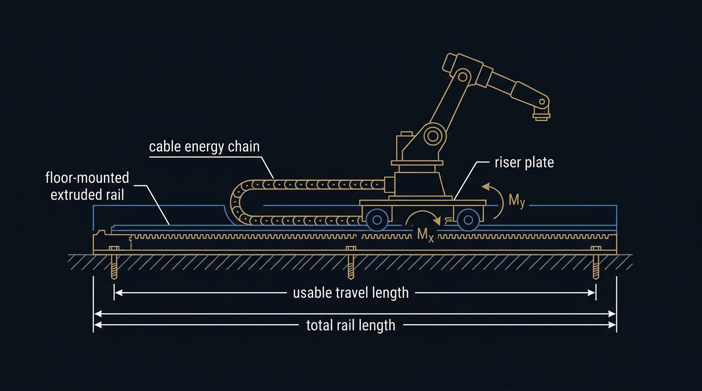
The first mistake in rail selection is reading "robot mass" from a datasheet and matching it to a "maximum payload" line. The rail does not carry a centered mass; it carries a tall, articulated mass that constantly changes shape. The robot's center of gravity sits several hundred millimeters above the carriage, and when the arm stretches horizontally, that CG moves sideways of the travel axis. The rail sees a vertical load plus two tilting moments — about the travel axis (Mx) when the arm reaches sideways, and across it (My) during acceleration and deceleration.
Example calculation — illustrative scenario, not a report of a Robotics Engineering Lab installation.All assumptions stated; recompute for your robot and posture before specifying.
Take a 250 kg industrial arm (mass from the robot datasheet) on a 60 kg riser, tending parts with a 30 kg combined wrist load. Assumptions: robot CG 0.35 m above the carriage top plane; arm horizontal at 1.2 m from the carriage centerline during the worst pose; maximum rail acceleration 3 m/s².
- Vertical load: (250 + 60 + 30) kg × 9.81 m/s² ≈ 3,335 N (750 lbf).
- Static tilting moment about the travel axis: the 250 kg robot at a 0.35 m CG height gives 250 × 9.81 × 0.35 ≈ 860 N·m; the 60 kg riser at 0.1 m adds ≈ 59 N·m; the 30 kg wrist load at a 1.2 m lateral offset adds 30 × 9.81 × 1.2 ≈ 353 N·m; total ≈ 1,272 N·m (938 lbf·ft).
- Dynamic addition: decelerating 310 kg moving mass (robot + riser + carriage, say 40 kg) at 3 m/s² produces a horizontal force of ≈ 930 N acting roughly 0.4 m above the guideway, adding ≈ 372 N·m to My.
- Design moment: the posture-dependent peaks combine to roughly 1.3–1.4 kN·m static plus dynamics, so a design value near 1.7 kN·m per bending axis is a defensible planning number — before any safety factor.
Applying a factor of 2 on moments (postures vary; integrators commonly plan well clear of capacity tables), this cell needs a track whose tables allow about 3.4 kN·m of tilting moment and 3.3 kN of vertical load. That lands in the light-to-mid range of manufacturer catalogs — but only the manufacturer's own moment-load diagram for your robot mass can confirm it. IPR's published seventh-axis data, for example, brackets its aluminum range at up to 7,000 N load and 9,000 N·m tilting moment, with steel and concrete ranges climbing to 150,000 N and 355,000 N·m.
Constraint 2: travel, speed, and acceleration
Travel is not rail length. Usable travel = total rail length − carriage length − hard-stop and bumper allowance at both ends − the clearance your guarding requires. When stations sit 2.2 m apart and you need three stations plus a home position with re-switch zone, the arithmetic adds up quickly; write the station map before the rail length.
Speed and acceleration decide whether one robot can serve N stations. For a trapezoidal velocity profile, move time over distance s at cruise speed v with acceleration a is approximately t = s/v + v/a (valid when the profile is trapezoidal, not triangular).
Example calculation (stated assumptions): stations 6.0 m apart, cruise speed 2.0 m/s, acceleration 3.0 m/s². Move time ≈ 6.0/2.0 + 2.0/3.0 = 3.0 + 0.67 ≈ 3.7 s each way. At a derated 1.5 m/s cruise: 4.0 + 0.5 = 4.5 s. Whether 0.8 s matters depends entirely on the cutting or process cycle being served — in a 95-second lathe cycle it is noise; between two press strokes it is the whole business case. Published catalog ceilings are higher than most cells use: Güdel's TMF-2 tables list 150 m/min (2.5 m/s) at 9,000 N and 90 m/min (1.5 m/s) at 25,000 N, with accelerations of 4 and 1.5 m/s² respectively; Rollon documents up to 3 m/s on steel units. Sustained maximum-speed duty also drives lubrication intervals and rack wear, so a rail sized "at catalog max all shift" is a maintenance plan, not a design.
Constraint 3: belt, rack and pinion, or ball screw drive
The drive type is the main architectural fork in a rail project, and it maps cleanly onto travel, mass, and duty.
| Drive type | Typical fit | Strengths | Limits |
|---|---|---|---|
| Rack and pinion | Industrial arms, multi-meter travel, high duty | Joinable rack for long and extendable strokes; handles robot-scale masses; robust in dirty environments with covers | Lubrication and wear management; more noise; pinion preload adjustment |
| Belt (open or sealed) | Cobot-class masses, shorter travel, cleaner floors | Quiet, low maintenance, clean; sealed versions for dirty environments (Rollon offers covered belt versions) | Tension maintenance and stretch under heavy duty; payload ceilings around cobot scale on published aluminum units |
| Ball screw | Short, stiff, precision strokes | High stiffness and positioning accuracy; simple | Length limited by critical speed; not for multi-meter robot travel |
For 6-axis arms on factory floors, rack and pinion is the default for a reason: strokes extend by bolting on another machined rack segment, and Güdel's and Rollon's seventh-axis ranges are built around it. Belt drives make sense under 3 to 4 m with light carriages. Ball screws belong in short-stroke positioning, not robot transfer. Repeatability across all three is far better than robot repeatability — published figures run from ±0.02 mm (Güdel dealer listings for small TMF units) through ±0.04 mm (Rollon steel RTU) to ±0.1 mm (IPR catalog) — so the drive choice is rarely decided by accuracy; it is decided by travel, mass, duty, and environment.
Constraint 4: structure, foundation, and flatness
A rail is a machine frame, and it obeys the same rule as a robot base: stiffness first. The manufacturer installation drawing specifies foundation depth, anchor type and pattern, grouting, and the flatness and level tolerance of the mounting surface over the full travel — commonly fractions of a millimeter per meter. A rail bolted to a thin, unreinforced slab will print floor waves directly into the guideway, and the symptom appears later as carriage bearing wear and station-to-station position offsets.
Plan four items with the civil work: a leveled strip footing or verified slab capacity for the carriage mass plus dynamic loads; shims and grout for flatness; anchor hardware per the drawing (not per the hardware store); and a repeatable mechanical reference — dowel pins or a machined datum edge — so the rail can be re-aligned after maintenance. Our robot arm base mounting guide covers the load-path discipline in detail, and every one of its flatness, torque-record, and commissioning arguments applies to a rail, just multiplied by travel length.
One structural point specific to tracks: joining. Long rails ship in sections with machined joints and joining kits. Section joints concentrate loads and are the first place to check when a rail develops vibration or repeatability drift at one station. Keep the joint torque record with the machine documentation.
Constraint 5: environment, covers, and lubrication
Seventh axes live on factory floors, and floors are full of what rails hate: abrasive dust, chips, weld spatter, coolant mist, and washdown water. The protection hierarchy is simple. Open rails suit clean, dry enclosures. Covered rails — telescopic way covers or a covered-belt design — suit machining and general industry; Rollon, for example, lists covered-belt versions of its aluminum transfer units specifically for dirty environments. Bellows-protected and purged designs suit the worst cases, and several manufacturers offer washdown-rated variants for food-grade floors.
Lubrication is the recurring cost that buyers skip. Rack-and-pinion drives need periodic grease on the rack — automated lubrication units controlled by the cell PLC are a standard option and pay for themselves on any multi-shift cell. Guideway carriages have wipers and lube points; IPR and Rollon both document single-point lubrication distribution as a design feature. Write the lubrication and inspection tasks into the cell maintenance schedule from day one, alongside the robot's own intervals; a dry rack wears silently until station positions drift outside the robot's re-mastering compensation.
Constraint 6: controls — coordinated external axis or discrete positioning
There are two control architectures for a seventh axis, and they change both the hardware list and the way the cell is programmed.
- Coordinated external axis. The rail servo is configured in the robot controller as an additional axis (joint 7). The controller coordinates rail and arm motion, can couple the rail to linear tracking moves, and shares the controller's safety functions and mastering. This is the standard for machine tending and welding. Budget for the external-axis hardware and software option on the robot controller, motor-to-cabinet cabling over the full travel, and per-station calibration.
- Independently positioned axis. A servo drive — often in a PLC-controlled cabinet — moves the carriage between fixed stations and hands the robot a "in position" signal through a handshake. Simpler in some retrofits, but every motion program must treat rail moves as discrete steps, and the safety concept must cover a carriage that can move without the robot controller commanding it.
Either way, three engineering items recur. Per-station base-frame calibration: the robot must re-establish its world frame at each station, typically with reference marks plus mastering, so TCP accuracy at station four does not inherit rail straightness error — our calibration guide covers the underlying accuracy-versus-repeatability logic. Home and reference switches: the rail needs its own homing routine, reference switch, and over-travel handling. And safety: emergency stop must remove power from the rail drive as well as the robot; enabling devices, safe-stop functions, and access interlocks must consider the whole swept envelope, which is why the risk assessment belongs to the integrated cell under ANSI/RIA R15.06, CSA Z434, and ISO 10218-2 rather than to the rail catalogue. Signal wiring between rail drive, robot controller, and cell PLC follows the same fieldbus choices as any other industrial cell — our PLC integration guide maps those options for North American panels.
The manufacturer landscape, from published data
Seventh axes are a specialist product category dominated by a handful of makers who publish capacity tables. The comparison below uses only figures published by the manufacturers themselves, accessed August 25, 2026; ranges summarize families, not one SKU.
| Maker / family | Body concept | Published capacity highlights | Notes from documentation |
|---|---|---|---|
| Güdel TrackMotion Floor (TMF) | Steel beam floor track, rack and pinion | TMF-2 tables: 9,000 N payload at 150 m/min and 4 m/s²; 25,000 N at 90 m/min and 1.5 m/s²; larger TMF sizes scale to heavy robots | Carriage and drive data published per stroke class; servo sizing tables included |
| Rollon RTU (aluminum) | Extruded aluminum transfer unit, belt or rack and pinion | Robots up to 1,500 kg; covered-belt versions for dirty environments; joinable, self-centering rack inserts for long strokes | Supplied with cable carrier, gearbox, automated rack lubrication as turnkey scope |
| Rollon RTU steel / RTUn | Steel body, rack and pinion | Speeds up to 3 m/s; repeatability 0.040 mm (± 0.020 mm) | Washdown, cleanroom, risers, multi-saddle options documented |
| IPR seventh axes | Aluminum, steel, and concrete-infill ranges | Loads 2,000 N up to 150,000 N; tilting moments to 355,000 N·m; speeds up to 3 m/s; accelerations up to 4 m/s²; repeatability ±0.1 mm | 2024 catalog PDF brackets classes by load and moment; walk-on versions available |
Read this table as orientation, not selection. Within one family the permitted robot mass depends on speed, acceleration, carriage count, riser height, and posture — exactly the moment calculation from Constraint 1. Robot manufacturers also bless specific track pairings for their arms, and integrators assemble the rest; a machine-tending cell combining one arm, two lathes, and a rail is exactly the architecture our machine tending guide analyzes from the timing side.
What a rail quotation must contain
Because tracks are configured to travel, load, and robot model, pricing is quote-dependent by nature; a single "typical price" would be false precision, so this section defines the line items instead. Quote required — and expect the quotation to show:
- Mechanics: rail sections to the ordered stroke, joining kits, carriage with rollers or guideway blocks, riser or pedestal to your robot's bolt pattern, hard stops and dampers.
- Drive train: servo motor, gearbox, pinion, and rack (or belt set), sized for your duty, with motor cable lengths over the full travel.
- Measuring and switching: position feedback (encoder scale or motor encoder with reference and limit switches) and over-travel handling.
- Energy chain and services: cable carrier, connectors, hoses, and the robot's own service loops so the dress pack survives years of travel — see our cable management guide for the bend-radius and fill rules that apply.
- Protection: covers or bellows, wipers, and any purging or washdown option.
- Lubrication: manual or automatic rack and carriage lubrication unit, with PLC control where specified.
- Controls: external-axis drive cabinet, robot-controller option, cabling, per-station calibration, and the integrator's engineering to close the handshake and safety concept.
- Delivery, installation, commissioning: section delivery schedule, foundation interface drawing, alignment, runoff criteria, spare parts list, and warranty terms as defined by the supplier.
Published industrial pricing for complete tracks is scarce by design; the only honest numbers are the components' list prices where a maker publishes them and the installed-cell ranges that integrators quote for whole projects. Treat any forum price as anecdote. For Canadian buyers, rail sections ship as oversize freight with cross-border implications — another reason the quotation, not a catalog price, is the real unit of information here.
Installation and commissioning checkpoints
A rail project is won or lost in alignment and calibration. The checkpoints below catch the failures that surface later as drift, vibration, or guarding gaps.
- Foundation acceptance: verify slab or footing, flatness over the full strip, and anchor layout against the manufacturer drawing before any rail section is set.
- Section alignment: straightness over total travel, joint gaps and torque, and level recorded at defined intervals — with a written record, not a verbal OK.
- Drive commissioning: servo tuning with the real robot mass aboard, acceleration limits set to the design value from Constraint 2, and over-travel tested gently.
- Switch and homing proof: reference switch repeatability, hard-stop behavior, and home routine after power cycle.
- Per-station calibration: master the robot at each station, record TCP check results, and verify that station-to-station error stays inside the process tolerance.
- Dress-pack endurance: run full-travel cycles and inspect the energy chain, service loops, and connectors for rubbing — the highest-frequency maintenance item on any track.
- Safety validation: e-stop verified to stop rail and arm; guarding or scanner zones proven along the entire travel, including both end positions; documented in the cell risk assessment.
Typical reader question: “Can I put a cobot on a belt-driven track and skip the foundation work?”Answered from published capacity data, not from an installation we performed.
Often yes for the rail itself — cobot-scale masses (an arm under 50 kg) sit comfortably inside published belt-drive transfer-unit ranges, and some suppliers sell exactly this package for machine tending. But "lighter rail" does not mean "no foundation logic." The track still needs a flat, rigid, anchored mounting surface over its full length; a belt track on an uneven slab loses its published ±0.1 mm-class repeatability in the first month. What you usually skip with a cobot track is poured concrete — not the flatness survey. Run the Constraint 1 moment check with the cobot's mass and riser; the numbers are smaller but the method is identical.
Sources and methodology
Capacity, speed, drive, and protection statements are drawn from manufacturer documentation accessed August 25, 2026: Güdel's TrackMotion Floor (TMF) product pages including the published TMF-2 stroke and drive tables; Rollon's RTU aluminum and steel robot transfer unit pages; and IPR's 2024 seventh-axis product information PDF. Standards context references ANSI/RIA R15.06, CSA Z434, and ISO 10218-2 as linked. The moment and move-time calculations are original worked examples with assumptions stated inline; they are planning arithmetic, not measurements, and Robotics Engineering Lab has not installed or tested any track. Foundation and commissioning practice synthesizes the installation requirements stated in the linked manufacturer documentation and general machine-installation engineering practice.
What does a seventh axis do for a robot arm?
A seventh axis is a motorized linear track that carries the whole robot between workstations, multiplying the work envelope along one direction. One arm can then serve several machines, presses, or weld stations in sequence, or reach along parts longer than its own reach. The rail is driven by a servo axis, either coordinated inside the robot controller as an extra joint or positioned separately by a PLC with a handshake.
How do I size a robot linear rail?
Size from four numbers: the vertical load (robot, riser, and payload weights), the tilting moments about the travel axis and across it with the arm fully extended, the travel length between hard stops, and the duty profile of speed and acceleration. Compare the calculated loads to the manufacturer capacity tables with a safety margin, typically at least two on moments, because the arm posture changes constantly during real cycles.
How fast can a robot travel on a seventh axis?
Published manufacturer data for floor tracks commonly reaches about 2 to 3 meters per second, with accelerations up to about 4 meters per second squared on smaller sizes. Güdel's TMF-2 tables list 150 meters per minute (2.5 m/s) at 9,000 N payload and 90 meters per minute at 25,000 N, and Rollon documents speeds up to 3 m/s for steel transfer units. Real cells usually run slower than the catalog maximum to control carriage dynamics and wear.
Rack and pinion or belt drive for a robot rail?
Rack and pinion suits long, heavy, high-duty tracks: strokes are extendable by joining rack segments, and it carries robot-scale masses. Belt drives are quieter, cleaner, and cheaper but stretch under high duty and are usually limited to lighter cobot-class tracks. Ball screws fit short, very stiff, high-precision strokes but not multi-meter robot travel, because screw length limits speed and critical speed.
Does a robot on a rail need a special foundation?
Usually yes. A floor track fastens to a leveled, grouted, and anchored foundation strip sized for the carriage mass plus dynamic loads, following the rail manufacturer's installation drawing for flatness, anchor type, and torque. Thin slabs often need a new footing. The preparation follows the same load-path discipline as robot base mounting: reaction loads must reach soil or structure without bending the rail.
How much does a seventh axis cost?
Robot tracks are configured products priced by travel, capacity, protection, and controls scope, so treat any single number as unreliable: quote required. A quotation should itemize rail sections and joining kits, carriage and riser, servo motor, gearbox, and rack, the measuring system, energy chain, covers, lubrication unit, external-axis integration in the robot controller, installation, and commissioning. Budget the controls and integration line explicitly, because it is a large share of the installed cost.