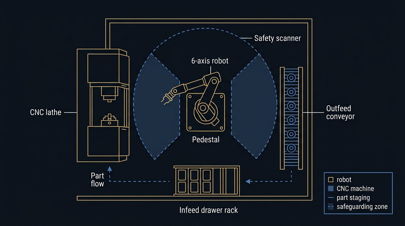
Editorial disclosure: Robotics Engineering Lab does not own or operate a machine-tending cell. This is a specification-based application guide compiled from manufacturer documentation, published integrator material, and public standards for readers in the USA and Canada. Cost figures are labelled published reference ranges, not quotations and not inventory.
What a machine tending cell actually has to do
Machine tending is the most common first automation project in North American machine shops, and it is also the one most often underspecified. The robot's job looks trivial — put a blank in, take a finished part out — but the cell is really a coordination problem between three machines: the robot, the machine tool, and the part-presentation hardware. A cell that only works when everything is perfect will not run unattended.
The cycle the robot must execute is longer than most buyers estimate. In a typical lathe cell it includes: confirming the machine has finished, waiting for the spindle to stop, opening the automatic door, reaching across the doorway, opening the chuck, extracting the finished part, clearing chips and coolant from the jaws, inserting the next blank, closing and verifying the chuck, retreating behind the door plane, closing the door, and requesting cycle start. Each of those steps can fail independently, and a cell designed only for the happy path stops the first time a chip sticks in a jaw.
FANUC America's machine-tending application pages describe the pattern that defines the application: the robot exists to raise spindle uptime and free operators for higher-value work, and the same arm can service secondary tasks such as deburring, gauging, cleaning, and inspection while the machine cuts. Universal Robots makes the same point in its machine tending application documentation, noting that tending is one of the most common cobot applications because the payload and reach requirements are modest and the cycle is repetitive. Those two manufacturer positions frame the central decision in this article: collaborative arm or fenced industrial arm.
This guide is organized around that decision and the constraints that drive it. It is a specification-based comparison: every number is either a worked calculation with stated assumptions or a published figure with a source and date.
The interfaces that size the robot before payload does
Buyers usually start with part weight, and part weight matters, but three interface constraints usually dominate the arm selection in real cells.
- Reach across the door plane. The arm must cross the machine doorway and reach the back of the chuck or the far vise. On a lathe with a 250 mm chuck, the deepest grasp point can sit 700 to 900 mm (28 to 35 in) behind the door face. Short arms solve this by reaching through the door at an angle, which costs cycle time and wrist capacity.
- Wrist load, not part mass. The wrist carries the gripper, a bracket, often a second offset gripper for raw and finished parts, and sometimes an air-blast nozzle. A 2 kg part can easily ride on a 12 kg tool. Size the arm from the combined payload and its center of gravity using the manufacturer's payload diagram, and check wrist moment and inertia limits the same way our end effector selection guide explains for the ISO 9409-1 flange.
- Speed and duty. A tending arm earns its keep during short windows: the unload-load exchange while the spindle waits. That means aggressive accelerations, thousands of orient changes per shift, and a duty profile closer to pick-and-place than to welding. Verify that the repeatability and path style you need (joint moves with blending, not linear Cartesian paths through the door) are natural for the arm.
A practical specification habit: write down the two extreme grasp points — deepest chuck grasp and highest staging-drawer grasp — plus the door plane, and check all three against the candidate arm's work envelope at the required wrist orientation. An arm that can reach the chuck only at full extension is a singularity-prone, slow cell. The same envelope reasoning that drives our payload calculator applies here, but with the door geometry added.
Cobot or fenced industrial arm: a decision matrix
The cobot-versus-industrial-arm question is not about which technology is better. It is about part weight, floor space, changeover frequency, and how much of the risk assessment the collaborative mode can actually carry. The matrix below is the core of this guide. It reflects published manufacturer capability ranges and the integration consequences of each choice.
| Decision factor | Collaborative arm (UR, FANUC CRX class) | Fenced industrial arm (LR Mate, IRB 1100/2600 class) | What tips the choice |
|---|---|---|---|
| Part plus gripper mass | Typically up to 20–30 kg payload class | 7–50 kg and beyond in the same floor space | Parts above the cobot class, or heavy dual grippers, decide immediately |
| Cycle time per exchange | Slower joint speeds; speed- and force-limited near people | Faster moves; full speed permitted inside guarding | Target exchange windows under ~20 s usually need an industrial arm |
| Changeover frequency | Designed for frequent reteach by operators | Changeover is possible but more often engineered per family | Job shops with daily part changes favor cobots |
| Floor space and guarding | Often no full fence; area scanner or no guarding after risk assessment | Perimeter fence or scanner-defined envelope required | Small shops with no space for a fence lean cobot |
| Coolant and chip exposure | Needs protective planning; see the maintenance section below | Standard IP67 wrists and dress protection available | Heavy coolant mist argues for industrial arms or hardened cobot setups |
| Reach into the machine | Typically 500–1,300 mm class reaches | Wider reach catalog; riser and rail options | Deep chucks and multi-machine layouts favor industrial arms |
| Integration effort | Low for one machine; kit ecosystem | Higher; integrator project with guarding and safety design | Internal capability decides as much as the hardware |
| Multi-machine expansion | Possible but reach and speed limited | Industrial arms pair naturally with a linear seventh axis | Three or more machines usually move to a rail-mounted industrial arm |
Read the matrix with one warning: the collaborative column is not automatically the safe column. A cobot tending an open machine inherits the machine's hazards — chips, coolant, a closing door, a hot finished part — and the risk assessment must treat the combined cell, not the arm alone. Conversely, a fenced industrial cell can be the lower-risk option precisely because access is controlled. Safety follows the risk assessment, not the marketing category, a point our USA and Canada robot safety standards guide covers in detail.
Part presentation: drawers, conveyors, trays, and bins
The second matrix in a tending project is part presentation — how raw blanks arrive and finished parts leave. This choice is driven by part mix and volume more than by the robot.
- Staging drawers and trays. The operator loads a matrix of blanks into a drawer; the robot picks positions in a taught grid. This is the default for low-mix job shops because the hardware is cheap and re-teaching a grid is fast. The gripper must tolerate small position variation, or the tray needs nests.
- Infeed and outfeed conveyors. Better for higher volumes of one part family. Conveyors decouple the operator from the cycle but add sensors, and the cell needs a strategy for parts that arrive rotated or overlapping.
- Vision bin picking. Removes the need for organized presentation, at the cost of a 3D vision system, more integration effort, and cycle-time penalties. It suits families of durable castings and forgings more than finished-machined surfaces that must not be scratched.
- Palletized finished goods. When parts are boxed or palletized after machining, the tending cell starts to resemble a palletizing cell, and stacking logic, layer patterns, and pallet change become part of the same project.
The engineering rule that survives every project: presentation determines uptime. A robot that tends the machine in 25 seconds but waits 90 seconds for an operator to reorganize a drawer has gained nothing. Count operator touches per shift as honestly as robot cycles.
Machine-side integration: doors, chucks, clamps, and signals
The machine tool side of the cell is where integration effort hides. Four items need explicit engineering.
Automatic doors. A servo or pneumatic door controlled by the handshake removes the robot from door duty and cuts several seconds per cycle. Retrospective door automation kits exist for common machine models, but confirm the door controller accepts remote open/close and reports a closed state, not just a commanded state.
Chuck and fixture state. The cell must confirm the chuck is open before the gripper enters and clamped before the door closes. Air-pressure switches on chuck lines are the minimum; some machines expose chuck status on the fieldbus interface. Never infer clamp state from the cycle-start signal.
Chip and coolant management. Chips pack chuck jaws and fixture seats. Most cells add an air blast or coolant rinse at the load position; some add a part-presence check. Budget the plumbing and the extra seconds.
The handshake itself. The signal set is the contract between robot and machine. The table below is the minimum set our readers should expect to see on an integration drawing.
| Signal | Direction | Meaning and failure handling |
|---|---|---|
| Cycle complete | Machine → robot | Spindle stopped, door may open; must be a real state, not a relay guess |
| Door open / closed | Machine ↔ robot | Two discrete states; a half-open door must read as not-closed |
| Chuck or fixture open / clamped | Machine → robot | Pressure-switch or fieldbus confirmed; robot inhibited when ambiguous |
| Cycle start request | Robot → machine | Latched request with robot-clear precondition |
| Robot clear of machine | Robot → machine | Maintained signal dropped by position or speed zone monitoring |
| Fault / e-stop shared state | Both ways | Any e-stop stops both; the cell restarts from a defined state, not mid-motion |
Whether those signals are wired discretely or carried over PROFINET or EtherNet/IP is an architecture choice our PLC integration guide treats in depth. The rule that does not change: standard PLC signals sequence the cell; safety functions — door interlocks, e-stop, mode selection — run through safety-rated hardware and software appropriate to the risk assessment.
Example calculation: can one robot tend two machines?
Example calculation — illustrative scenario, not a report of a Robotics Engineering Lab installation.Assumptions stated inline; verify timing against your machines before committing hardware.
Consider a small turning cell: two CNC lathes, 2.4 m (7.9 ft) apart, each cutting a family of 2.1 kg steel blanks on a 95-second cutting cycle. The candidate robot is a 20 kg-class industrial arm. Question: can one arm keep both spindles loaded, and what spindle utilization results?
Assumptions (all stated, all adjustable): door open/close 4 s each way; robot unload move to handoff 8 s; chuck clean with air blast 3 s; load blank 8 s; robot retreat behind door plane 4 s; robot travel between machines 4 s average; gripper carries dual fingers so raw and finished parts move in one exchange.
Tending time per machine visit: 4 (door) + 8 (unload) + 3 (clean) + 8 (load) + 4 (retreat) + 4 (door) = 31 s. Two machines per cutting cycle: 2 × 31 s + 4 s transfer = 66 s of robot work per 95-second cut window. The arm has 29 s of slack — enough for a gauging stop or staging pickup, not enough for a second process. The timing closes.
Spindle utilization per machine: the spindle waits only during its own 31-second tending window, so utilization ≈ 95 / (95 + 31) = 77.9%. With one machine the same cell yields the same 77.9% and strands the robot for 95 s per part; the second machine nearly doubles output for the price of a second door interface and 4 s of transfer time. This arithmetic — not vendor claims — is what should enter an ROI model such as the one in our robot arm ROI calculator. If the cutting cycle were 45 s instead of 95 s, the same robot could no longer serve two machines (66 s of work does not fit a 45 s window), and the honest options become a faster exchange, a second robot, or one machine only.
Coolant, chips, and the environment nobody budgets for
Machine-tending robots live in coolant mist, and coolant is the quiet reliability problem of the application. Universal Robots publishes maintenance recommendations for CNC tending that state the issue directly: long-term exposure to cutting fluid can reduce cobot performance, and UR recommends path planning that limits exposure plus chemical-resistant joint lid upgrades for continuously exposed machines. FANUC similarly offers washproof variants of its small arms for wet machining environments.
Three practices follow for any arm class. First, plan paths that enter and leave the machine envelope quickly rather than dwelling in the mist zone; every second of dwell is exposure. Second, treat dress packs, connectors, and gripper wiring as consumables — coolant wicks into cable strain reliefs long before joints fail. Third, add scheduled wiping and seal inspection to the preventive maintenance plan; our 6-axis maintenance schedule gives the inspection framework, and tending cells typically tighten the interval rather than relax it.
Chips are the second environmental load. Stringy chips wrap around chuck jaws and gripper fingers; cast-iron dust contaminates linear guides if the cell later adds a rail. Specify wipers, covers, and an air-blast as part of the cell, not as a retrofit after the first jam.
Safety responsibilities at the machine boundary
A tending cell is an integrated robot system, and in both the USA and Canada that integration — not the arm alone — is what standards regulate. In the USA, ANSI/RIA R15.06 adopts the international requirements of ISO 10218-2 for the integration of the robot into the cell; in Canada the applicable document is CSA Z434. The machine tool itself is guarded under machine-tool safety practice in the ANSI B11 series and occupational rules; OSHA's robotics technical manual is the practical starting point for US employers, with provincial regulators playing the equivalent role in Canada.
Four boundaries recur in tending risk assessments. Access to the machine envelope: operators must be able to clear a jammed part, which usually means an interlocked gate or scanner zone that stops the cell safely rather than a locked door that invites defeat. Teach and manual modes: door-open jogging for setup must be speed-limited and controlled. Restart after fault: the cell must resume from a defined state with the machine and robot agreeing on where the part is. And servicing: lockout/tagout applies to machine, robot, and any powered staging hardware before anyone reaches into either envelope. These are educational summaries, not a risk assessment; use a qualified integrator or controls engineer and the current editions of the standards for any real cell.
Typical reader question: “My lathe door is manual. Do I have to automate the door before I can use a robot?”Answered from integration practice, not from one project.
Not necessarily, but the robot must be able to open it. Two workable patterns exist. In the first, the robot itself operates the manual door with a dedicated door tool or hook grasp — cheap, but it costs 6 to 10 seconds per cycle and consumes wrist capacity. In the second, a door automation kit converts the door to servo or pneumatic operation under handshake control — faster and cleaner, at the cost of a machine modification that should be approved by the machine-tool builder. What does not work long-term is a cell whose door state is inferred from a timer.
What a machine tending quotation should contain
Machine tending is a configured system, so pricing is quote-dependent by nature. Rather than publishing a fake street price, this section defines what a defensible quotation must itemize, then lists the published reference ranges we could verify.
- Robot package: arm, controller, teach pendant, cable length, and the payload/reach class you specified.
- End of arm tooling: gripper, fingers or fixtures across the stated part family, part-presence sensing, and quick-change options.
- Machine interfaces: door automation, chuck sensing, handshake I/O or fieldbus modules at each machine.
- Part presentation: drawers, trays, conveyors, or vision hardware and its integration.
- Safeguarding: fence or scanner hardware, safety controller, interlocks, and the verification activities for them.
- Controls and software: PLC or safety PLC program, robot program with fault handling, HMI, and any machine-side programming by the machine-tool builder.
- Engineering, commissioning, and runoff: hours stated explicitly, with acceptance criteria — cycle time, uptime over a trial run, fault recovery demonstrated.
- Training, spares, and warranty terms: as defined by the integrator's contract.
Published reference ranges, with sources and dates: a US integrator's 2026 application page places a typical single-machine CNC tending cell with a FANUC robot, conveyor staging, and basic gauging at approximately 150,000 to 250,000 USD, and multi-machine cells with rail systems and advanced gauging at 300,000 to 500,000 USD, with payback quoted at 8 to 16 months on two-shift operations. Cobot-oriented suppliers have published 2026 guides advertising complete lights-out setups in the 60,000 to 150,000 USD range. Treat all of these as Indicative 2026 reference ranges from public sources, not quotations — they vary with part weight, machine count, guarding, and labor market, and none of them is Robotics Engineering Lab inventory. For Canadian projects, budget the same ranges in USD plus import, duty, and installer travel, and request CAD pricing from integrators directly; we do not publish a CAD conversion because exchange rates move.
Commissioning checkpoints before the first unattended cycle
Acceptance is where tending projects are won. The checkpoints below turn “it ran a demo” into “it runs a shift.”
- Handshake proof, signal by signal: force each abnormal state (half-open door, unclamped chuck, dropped part-present sensor) and confirm the cell stops in the designed safe state, every time.
- Timing closure: measure the real tending window against the calculation. If the measured exchange exceeds the planned window by more than about 10%, revisit door speed, blending, and approach poses before adding machines.
- Changeover rehearsal: change to a second part from the stated family and measure changeover time with the actual operator, not the integrator's engineer.
- Failure-mode walk-through: intentionally jam a blank, stick a chip, and fault the machine mid-cycle; the cell should recover or fail safely and report, not collide.
- Endurance runoff: a defined shift-length or longer run with uptime logged against the acceptance criterion agreed in the quotation.
- Safety verification and documentation: the risk assessment, validation report, and operating instructions delivered and reviewed with the operators who will run it — the human-factors layer our operator training guide develops.
Sources and methodology
Application capabilities, cobot maintenance guidance, and cell-configuration patterns are drawn from manufacturer and integrator documentation accessed August 25, 2026: FANUC America's machine-tending application pages, Universal Robots' machine tending application page and CNC tending maintenance recommendations, and published 2026 integrator cost pages (AMD Machines; Graba Robot) used only for clearly labelled reference ranges. Safety boundaries summarize ANSI/RIA R15.06, CSA Z434, ISO 10218-2, and OSHA's robotics technical manual as linked above; consult the current editions — the 2025 revision cycle of the ISO 10218 series is rolling into national adoptions — and a qualified integrator for any real deployment. The two-machine timing example is an original illustrative calculation with all assumptions stated in the text; it is not a measurement from an installed cell. Robotics Engineering Lab has not purchased, installed, or tested any of the equipment named in this article.
What size robot do I need for machine tending?
Size the robot from the total wrist load, not just part weight. Add the part, the gripper, any dual-gripper bracket, and the reach needed to cross the machine door and reach the chuck or fixture. A common single-gripper lathe cell with parts under 5 kg uses a 7 to 20 kg class arm, while longer reaches into horizontal machining centers push the selection toward 20 to 50 kg class arms. Verify the wrist moment and inertia limits against the manufacturer payload diagram before buying.
Can a collaborative robot tend a CNC machine without fencing?
Sometimes, but only after a documented risk assessment. A cobot can remove the operator from the machine door, yet the hazard is not only the arm: the machine tool, sharp chips, coolant mist, ejected parts, and hot workpieces remain. Many cobot tending cells still need area scanning, interlocked access, or partial guarding. Collaborative operation does not remove the need to comply with ANSI/RIA R15.06 in the USA or CSA Z434 in Canada.
Is machine tending viable in a low-mix job shop?
Yes, when the cell is designed for changeover rather than for one part number. The practical requirements are a gripper that spans the part family or quick-change fingers, re-teachable staging positions, and a part program interface that an operator can update without a programmer. Cells that need a new fixture and new code for every job usually stall after the first few parts.
What signals must pass between the robot and the machine tool?
At minimum: cycle complete, door open and closed, part or chuck clamped confirmation, cycle start request, robot clear of the machine, and a fault or e-stop state shared both ways. Most integrators implement this as a discrete I/O handshake or as fieldbus messages over PROFINET or EtherNet/IP, with safety-rated signals kept on a safety controller rather than the standard PLC program.
How much does a machine tending cell cost?
Published 2026 integrator estimates place a basic single-machine cell around 150,000 to 250,000 US dollars, and multi-machine cells with a linear rail and gauging around 300,000 to 500,000 US dollars, while cobot-based packages have been advertised from roughly 60,000 to 150,000 US dollars. These are reference ranges from public sources, not quotations. A firm price depends on part weight, machine interfaces, staging hardware, guarding, and commissioning scope, so request itemized quotes.
What happens when the machine faults during unattended running?
The cell should fail to a defined safe state: the robot stops clear of the machine, the cycle start is inhibited, and the cell reports an alarm to a phone, monitoring system, or MES. The handshake design must cover every abnormal exit, including a door that only half opens, a part stuck in the chuck, and a machine stop mid-cycle. Lights-out reliability comes from handling these faults explicitly, not from hoping they do not occur.