Disclosure and scope: this is a specification-based selection guide, not a test report. Robotics Engineering Lab has not bought, wired, measured or bench-tested any of the motors, drivers or power supplies named here. Every specification and price is taken from the manufacturer datasheet or distributor page cited in the sources section, with the access date recorded. Calculations shown are worked examples with stated assumptions, not measurements. Nothing here approves a machine or substitutes for the manufacturer documentation for your specific parts.
Where a stepper motor fits in a robot arm drivetrain
A hybrid stepper motor is a two-phase permanent-magnet brushless machine with a high pole count. The common 1.8° version has 50 rotor teeth and takes 200 full steps per revolution. The controller energises the two windings in a fixed sequence and the rotor snaps to each detent in turn. There is no position sensor, no error signal and no control loop: the motor is assumed to be exactly where the step count says it is. That assumption is what makes a stepper cheap and what makes it fragile.
Our servo motor guide covers the other three actuator families used in robot arms — PWM hobby servos, digital bus servos and industrial AC servos. A stepper is a fourth family with a different trade. It gives you full continuous rotation (a standard hobby servo is limited to roughly 180°), high torque at zero speed, deterministic open-loop positioning and drivers that cost a few dollars. It takes away torque at speed, silent failure under overload, mid-speed resonance, and continuous copper loss even when the joint is not moving. On an educational or research 6-DOF arm, and on any joint that moves slowly and holds a known load, those trade-offs are usually the right ones.
The rest of this article works through the selection constraints in the order that actually eliminates candidates. Torque first, because nothing else matters if the joint cannot lift the link. Then speed, then dynamics, then resolution, then the driver, then thermal behaviour, and finally the feedback decision.
Requirement 1: static holding torque at the worst pose
Start with the static case, because it is the only one you can compute without knowing the motion profile. Gravity torque at a revolute joint is the sum of each mass times the perpendicular horizontal distance from the joint axis to that mass’s centre of gravity. The worst pose is the one where every link downstream of the joint is horizontal.
Add joint friction, cable and harness drag, and any process force the tool applies. Then apply a service factor. For a slow educational arm with a known, fixed payload, a factor of 1.5 to 2.0 on static torque is normal practice. If a person can push on the arm, if the tool can snag, or if the arm must hold position against an external load for long periods, size for more and prefer closed-loop control.
Watch the units, because stepper and servo datasheets do not agree. Stepper holding torque is published in N·cm or oz·in; hobby servo torque is published in kg·cm. The conversions are 1 oz·in = 7.0616 mN·m and 1 kg·cm = 98.07 mN·m. A 59 N·cm motor is 0.59 N·m, which is roughly the same as a 6.0 kg·cm servo rating — not 59 kg·cm. Getting this conversion wrong by a factor of ten is the single most common stepper sizing error we see in reader questions.
Requirement 2: the torque–speed curve is the spec that actually sizes the joint
Holding torque is measured at standstill, with rated current in the windings and the rotor stationary. It tells you nothing about what the motor can do at 600 rpm. Pull-out torque — the torque the motor can deliver without losing steps at a given speed — falls off steeply with speed, and the fall-off is set by the electrical time constant of the winding.
This is why stepper drivers are run at 24 V or 48 V rather than at the motor’s rated winding voltage. The #2267 above is rated at 2.8 V per phase; you would never power a robot arm bus at 2.8 V. The driver regulates current by chopping, and the supply voltage is the headroom that forces current into the inductance quickly enough. Higher bus voltage buys torque at speed at the cost of more dissipation in the driver and more heat in the motor. The Pololu DRV8825 carrier is rated 8.2–45 V and the A4988 carrier 8–35 V; the ADI/Trinamic TMC2209 is rated 4.75–29 V.
The practical consequence for a selection guide is blunt: never size a robot joint from the holding-torque number alone. Find the manufacturer’s published torque–speed curve for that motor at the supply voltage you intend to use, and read the torque at the motor speed your gear ratio produces. If the datasheet only shows a curve at 24 V and you plan to run 48 V, treat the published curve as conservative. If it shows only a curve at 12 V and you plan to run 24 V, you can do better but you have no published number, so verify by test.
Requirement 3: acceleration, rotor inertia and the reflected load
Static torque holds the arm. Acceleration torque moves it. The total torque the motor must produce during a move is the acceleration torque plus the gravity torque at that instant:
Two things fall out of that equation and both matter more than the peak torque number. First, reflected load inertia falls with the square of the ratio: a 10:1 reduction divides the load inertia seen by the motor by 100. Second, a stepper does not need inertia matching in the way a closed-loop servo drive does — there is no loop to destabilise — but a high reflected inertia with a short acceleration ramp is exactly the condition that produces lost steps. Use a trapezoidal or S-curve velocity profile, keep the acceleration ramp long enough that the demanded torque stays inside the pull-out torque curve, and verify by running the profile with a deliberate overload test.
Published rotor inertia for a NEMA 17 hybrid stepper is of the order of 10−6 kg·m², but it varies enough between models that you should read the value from the datasheet rather than assume it. Our belt drive versus gear drive comparison covers the reduction side of this equation, including the backlash penalty each stage adds to joint accuracy.
Resolution: step angle, microstepping and what microstepping does not do
A 1.8° motor gives 200 full steps per revolution. A 0.9° motor gives 400 and buys finer resolution at some cost in holding torque and in inductance. Microstepping then divides each full step by driving the two phase currents as partial sinusoids rather than full on or full off. Pololu describes the mechanism accurately: intermediate step locations are achieved by energising the coils with intermediate current levels.
Microstepping genuinely improves two things: commanded resolution, and smoothness. It reduces the torque ripple that causes vibration and audible noise, which is why quiet drivers such as the TMC2209 default to fine microstepping. What microstepping does not do is proportionally improve accuracy. Each additional microstep produces a smaller increment of torque. When that increment falls below the joint’s static friction plus the motor’s detent torque, the rotor simply does not move, and the commanded position and the actual position diverge. Detent torque — the residual torque present with the phases unpowered — is typically a few percent of holding torque. In practice, most hobby-scale arm joints stop gaining real positional improvement somewhere between 1/8 and 1/16 microstepping. Beyond that you are buying smoothness, not precision.
The other property people assume a stepper has and it does not: absolute position. A stepper motor does not know where it is at power-up. Every stepper-driven joint needs a homing routine — an optical or magnetic limit switch, a mechanical hard stop with a deliberate stall, or a sensorless stall-detection reference. Budget the switch, the wiring and the code, and design the mechanism so that homing cannot damage it.
Choosing the driver: current setting, supply voltage and chopper mode
The driver sets the phase current, generates the step sequence and protects the motor. Three widely used families cover almost every hobby and educational arm:
| Driver | Supply voltage | Current per phase | Microstepping | Notable features |
|---|---|---|---|---|
| A4988 carrier (Pololu #1182) | 8–35 V | 1 A continuous, 2 A peak | to 1/16 | Cheapest usable option; no stall detection |
| DRV8825 carrier (Pololu #2133) | 8.2–45 V | 1.5 A continuous, 2.2 A peak | to 1/32 | Higher voltage headroom; drop-in replacement for A4988 |
| TMC2209 (ADI/Trinamic) | 4.75–29 V | 2 A RMS, 2.8 A peak | 256 by microPlyer interpolation | StealthChop2, SpreadCycle, CoolStep, StallGuard4, single-wire UART |
Set the current limit from the motor’s rated phase current, not from the driver’s maximum. For the TMC2209 the datasheet gives the relationship between the reference voltage and the phase current as IRMS = [325 mV / (RSENSE + 20 mΩ)] × (1/√2) × (VREF / 2.5 V). With the 110 mΩ sense resistors used on most carrier boards this reduces to IRMS = VREF/√2 and Ipeak = VREF, so a 1.4 V reference sets roughly 1.0 A RMS. Always use the formula printed on the specific carrier you bought, because sense-resistor values differ between boards and an incorrect setting cooks motors.
Chopper mode matters more than most buyers expect. StealthChop2 is a voltage-mode chopper that makes low-speed motion near-silent; SpreadCycle is a mixed-decay current chopper that is more dynamic but noisier. The TMC2209 can switch between them automatically at a programmable velocity threshold, which is the behaviour you want on an arm joint that dwells slowly and then accelerates hard. CoolStep reduces phase current when the load is light and is the single most effective way to keep a stepper-driven arm from becoming a space heater. StallGuard4 provides sensorless stall detection, usable for homing and for detecting a collision — but it is sensitive to speed and temperature and must be tuned per axis.
Thermal and acoustic limits: a motor that runs is not a motor that lasts
A stepper dissipates near its rated copper loss continuously, including while holding still with the phases energised. That is the opposite of a servo, which draws current in proportion to load.
Eleven watts in a 42 mm frame is substantial. Most NEMA 17 hybrid steppers are built to insulation class B, rated 130 °C, which protects the winding but says nothing about the surface being safe to touch or about the plastic parts mounted next to it. Measure the case temperature in continuous duty and keep it well below the winding limit; a case above roughly 70–80 °C in still air is the point to reduce current, add airflow, or move to a larger frame. On the acoustic side, once the driver is in a quiet chopper mode the dominant noise source usually moves downstream to the reduction stage and any belt in the path, not the motor itself.
Resonance deserves its own note. Hybrid steppers have a resonant band, typically in the low hundreds of rpm at the motor shaft, where vibration and noise spike and step loss becomes likely. The standard mitigations are finer microstepping, higher bus voltage, a mechanically damped mount, and — most importantly — motion profiles that accelerate through the band rather than dwelling in it. If your arm spends a lot of time at one constant low speed, expect to find that band and design around it.
Open loop, sensorless stall detection, or closed loop with an encoder
There are three tiers of position assurance available for a stepper-driven joint, and the right choice depends entirely on what a lost step costs you.
- Pure open loop. Cheapest and simplest. Steps are counted and assumed. A stall produces no fault, no alarm and no recovery — the arm is simply wrong from that moment until the next homing. Fine for a bench arm that nobody can reach and nothing can collide with.
- Sensorless stall detection. A driver such as the TMC2209 estimates back-EMF and reports a stall on its DIAG pin. This gives you a homing reference without a switch and a crude collision alarm. It is velocity- and temperature-dependent, needs per-axis tuning, and is not a position measurement. Do not describe it to a reviewer as closed-loop control.
- Closed-loop stepper. An incremental encoder on the motor shaft closes a position loop inside the driver. Typical hobby-grade kits use a 1000 PPR (4000 CPR) optical encoder. The driver corrects lost steps, reduces holding current when the joint is unloaded, and reports a real fault. This is the tier to choose whenever a lost step has a consequence — a dropped part, a collision with a fixture, or an unrecoverable position error.
There is a crossover point, and it arrives sooner than people expect. Once you pay for a closed-loop stepper driver, an encoder and the tuning time, the total cost approaches that of a small brushless servo with an integrated encoder, and the servo will out-torque the stepper at speed. If your joint needs sustained speed, variable load or real dynamic response, stop optimising the stepper and read the servo comparison instead. The joint encoder guide explains the absolute, incremental and magnetic feedback options if you go that way.
Illustrative scenario: sizing one shoulder joint
Example calculation — planning arithmetic with stated assumptions, not a measurement from a Robotics Engineering Lab bench.Substitute your own link masses, lever arms and motion profile before selecting a motor.
Assume a small 6-DOF educational arm. The forearm and everything downstream of joint 2 has a mass of 0.40 kg with its centre of gravity 0.12 m from the joint axis. The end effector plus payload has a mass of 0.25 kg at 0.28 m. Worst pose: both horizontal.
Now compare that against real catalogue parts. A NEMA 17 rated at 59 N·cm holding torque gives a standstill margin of about 2.6× on the required 23.1 N·cm. That looks comfortable and it is not, because holding torque is a standstill number. At the motor speed this joint will actually run — 60 rpm at the output through a 10:1 is 600 rpm at the motor — pull-out torque on a typical NEMA 17 is often close to half the holding value, so the working margin is nearer 1.3×. That is a defensible design for a slow educational arm with a known payload. It is not a defensible design if the payload varies, if the arm must hold against a push, or if a lost step would drop a part.
Notice what the calculation did not need: a part number. The output of joint sizing is a torque requirement at a speed, expressed in N·cm at the motor shaft. Only then do you open a catalogue and read the torque–speed curve at your chosen supply voltage. Our payload calculator does the equivalent arithmetic for industrial arms, where wrist moment limits rather than motor torque become the binding constraint.
A per-joint starting point for a 6-DOF arm
| Joint | Dominant load | Practical starting choice | Why |
|---|---|---|---|
| J1 base rotation | Full arm inertia about a vertical axis; no gravity moment | NEMA 17 or NEMA 23 with 3:1–5:1 reduction | Inertia-dominated, so acceleration ramp matters more than holding torque |
| J2 shoulder | Full gravity moment of arm plus payload | NEMA 23, or NEMA 17 with 10:1 or higher | Highest static torque demand in the arm |
| J3 elbow | Forearm and payload gravity moment | NEMA 17 with 5:1–10:1 reduction | Usually the second-highest static demand |
| J4 wrist roll | Tool inertia about the tool axis | Small NEMA 17 or NEMA 14 | Low torque, but continuous rotation needs a slip ring or a cable plan |
| J5 wrist pitch | Tool and payload at short lever | Small NEMA 17 with light reduction | Speed matters more than torque here |
| J6 tool rotation | Very low torque | Small NEMA 14 or a bus servo | Often better served by a smart servo than a stepper |
Two structural notes. First, the base joint is the one people oversize: with the axis vertical there is no gravity moment at all, only inertia, so the requirement is acceleration rather than holding torque. Second, continuous-rotation joints (J1 and J6) need a cable strategy before they need a motor. Route the harness through a slip ring or leave a deliberate service loop, and treat that as part of the design rather than something to solve after the arm is built.
Indicative 2026 component prices (USD)
| Item | Specification | Indicative 2026 price (USD) | Source |
|---|---|---|---|
| Pololu #2267 NEMA 17 stepper | 42×38 mm, 1.68 A/phase, 3.7 kg·cm (0.36 N·m) holding, 1.65 Ω, 3.2 mH | $35.12 (qty 1) | Pololu product page |
| Pololu #1200 NEMA 17 stepper | 42×48 mm, 1.2 A/phase, 3.2 kg·cm (0.31 N·m) holding, 3.3 Ω, 2.8 mH | $43.12 (qty 1) | Pololu product page |
| Pololu #1182 A4988 driver carrier | 8–35 V, 1 A continuous per phase | $8.95 (qty 1) | Pololu product page |
| Pololu #2133 DRV8825 driver carrier | 8.2–45 V, 1.5 A continuous per phase, 1/32 microstepping | $15.95 (qty 1) | Pololu product page |
| Closed-loop NEMA 17 kit (StepperOnline 1-CL42T-S05-V41) | 52 N·cm motor with 1000 PPR encoder plus CL42T-V41 driver, 24–48 VDC, 0–3.0 A | $48.86 (qty 1) | StepperOnline product page |
| Mean Well LRS-150-24 supply | 24 V, 6.5 A, 156 W enclosed AC-DC | Reference range $18–$24 | Bravoelectro ($18.40) and TRC Electronics ($23.31 for the LRS-150F-24 variant) |
| Arduino Mega 2560 Rev3 | ATmega2560, 54 digital I/O, 4 UARTs | $55.00 | AndyMark product page |
These are United States list prices in US dollars. Canadian readers should expect currency conversion, duties and brokerage on cross-border orders, and should confirm the shipping price at checkout; Robotics Engineering Lab did not verify Canadian distributor listings for these parts, so no CAD figure is quoted here. Prices on hobby components move frequently and distributor price breaks are significant — the Pololu motors above drop roughly 6% at five units and 12% at twenty-five.
Power budget: how to size the supply for six stepper joints
Stepper current draw does not add the way resistive loads do. A chopped constant-current driver draws less average input current than the phase current it delivers, because the chopping duty cycle depends on supply voltage, winding resistance and speed. There is no substitute for measuring, but a defensible planning estimate is:
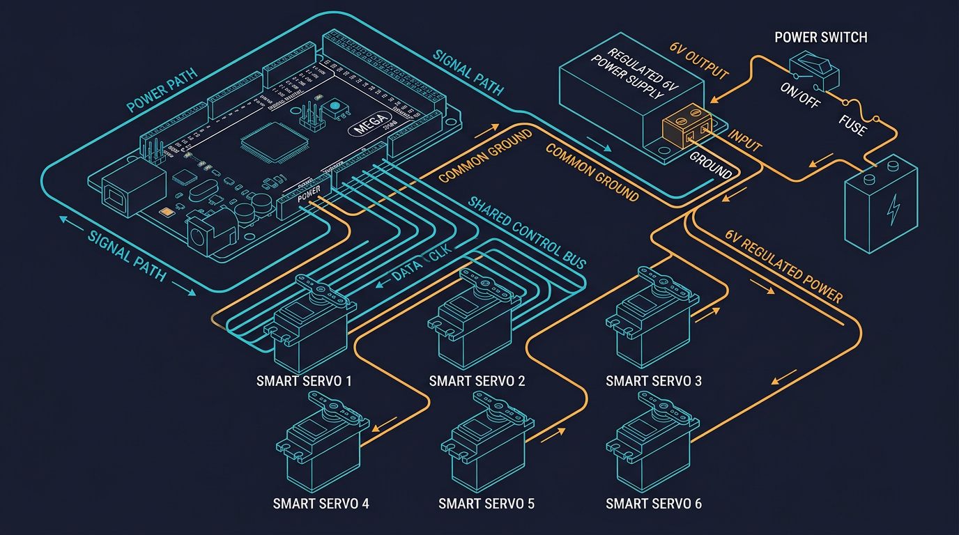
The 0.7 factor is a planning assumption, not a measurement, and it is optimistic when all axes accelerate simultaneously into a high-torque pose. Size for the simultaneous case, not the average case, then verify with a clamp meter on the DC bus during the worst move in your motion profile. Use a supply with real short-circuit and over-temperature protection, fuse the DC bus, and keep motor and logic grounds bonded at a single point. Our Arduino Mega wiring guide works through the same method for a bus-servo arm, including wire gauge and termination practice.
When a stepper motor is the wrong answer for a robot arm
Being honest about the boundary is part of the selection. Choose a different actuator when any of the following is true:
- The joint must hold position with power removed. A stepper holds only while energised. Detent torque is a few percent of holding torque and will not support a link. You need a brake, a worm or lead-screw transmission with enough friction to self-lock, or a counterbalance.
- The joint must run fast, continuously. Above roughly 1000 rpm at the motor shaft, pull-out torque on a hobby-scale stepper is small and the efficiency is poor. A brushless servo with a reduction is the correct part.
- The payload varies or is unknown. Open-loop control has no way to notice that the torque margin has vanished. Either close the loop or size for the worst case and accept the cost.
- A lost step has a safety or quality consequence. Silent failure is a design property of open-loop control, not a bug. If the consequence matters, use closed-loop feedback and treat the fault signal as real.
- The duty cycle is high. Continuous holding loss makes steppers the least efficient way to hold a static position. Servos and brakes both beat them here.
- The arm is an industrial cell with people near it. Industrial robot arms use closed-loop AC servos with safety-rated control for a reason. Nothing in this article is guidance for a production cell; that work belongs with a qualified controls engineer or integrator and the current edition of the applicable robot safety standard.
Sources and methodology
Motor and driver specifications and single-unit prices were taken from the Pololu stepper motor driver comparison table and from product pages for items #1200, #2267, #1182 and #2133, and from the StepperOnline product page for kit 1-CL42T-S05-V41, all accessed August 27, 2026. The category comparison is the most useful official source here because it prints each driver’s continuous current alongside the exact test condition — on the carrier board, at room temperature, without additional cooling — which is precisely the condition the current figures in this article assume, and the condition under which a datasheet peak figure would overstate what the board will sustain. TMC2209 electrical specifications, the VREF-to-current relationship and the CoolStep, StallGuard4 and StealthChop2 feature set are from the Analog Devices / Trinamic TMC2209 datasheet, Rev. 1.03. Power-supply prices are from Bravoelectro and TRC Electronics listings accessed the same day and are shown as a reference range rather than a single figure. The Arduino Mega 2560 Rev3 price is from AndyMark. Formulas for gravity torque, reflected inertia and resolution are standard mechanics; the electrical time-constant and standing-loss arithmetic shown in this article were computed from the datasheet values printed alongside them, and every assumption is stated in the block. Robotics Engineering Lab has not bench-tested these motors, has not measured the torque–speed curves, and does not stock or sell any of the components listed. The joint table is a starting point for planning, not a validated specification.
Frequently asked questions
Can a stepper motor hold a robot arm joint in position with the power off?
No. Holding torque only exists while the phases are energised, so cutting power releases the joint. Detent torque from the permanent magnet is typically only a few percent of holding torque and will not support a link against gravity. If the joint must stay put unpowered, add a brake, use a worm or lead-screw stage with enough friction to self-lock, or fit a mechanical counterbalance.
Does 1/256 microstepping make a robot arm joint 256 times more accurate?
No. Microstepping increases commanded resolution and smoothness, but accuracy is limited by torque per microstep, static friction and detent torque. Once the incremental torque of one microstep falls below the friction in the joint, the rotor does not move and the commanded and actual positions diverge. Most hobby-scale arm joints stop gaining real improvement between 1/8 and 1/16 microstepping; beyond that you are buying quieter motion.
Why does my stepper lose steps at speed but hold position fine when it is slow?
Because phase current cannot reach its set point within the step period. The winding inductance and the motor back-EMF limit how fast current can change, so torque falls off with speed. Raise the supply voltage within the driver rating, lengthen the acceleration ramp, reduce the microstep rate for high-speed moves, and verify against the manufacturer torque-speed curve at your actual bus voltage rather than the holding-torque figure.
What supply voltage should a stepper-driven robot arm use?
As high as the driver rating and your thermal budget allow, not the motor rated winding voltage. A Pololu A4988 carrier is rated 8 to 35 V, a DRV8825 carrier 8.2 to 45 V, and a TMC2209 4.75 to 29 V. Higher voltage gives more torque at speed because it forces current into the winding inductance faster, at the cost of more dissipation in the driver and more heat in the motor. Never exceed the driver maximum, and allow headroom for inductive voltage spikes.
Do I need a closed-loop stepper for a six-DOF robot arm?
It depends on what a lost step costs. A pure open-loop joint fails silently: no fault, no alarm, and the arm is wrong until the next homing routine, which is acceptable on a bench arm nothing can collide with. Add sensorless stall detection if you only need homing and a crude collision alarm. Choose a real closed-loop stepper with an encoder when a lost step could drop a part, hit a fixture, or leave the arm in an unrecoverable position.
How do I size the power supply for six stepper joints?
Sum the rated phase current times two phases for every motor, derate by a planning factor of about 0.7 to allow for chopper duty, then apply an 80 percent loading rule to the supply rating. That estimate is optimistic when all axes accelerate together into a high-torque pose, so size for the simultaneous case and confirm with a clamp meter on the DC bus during the worst move in your motion profile.